
System and method for dealing with component obsolescence in microprocessor-based control units

a control unit and microprocessor technology, applied in the field of vehicle control systems, can solve the problems of inability to ensure the continuous supply of microprocessors, and inability to meet the requirements of vehicle manufacturers,

Inactive Publication Date: 2006-12-14
BAYERISCHE MOTOREN WERKE AG
View PDF12 Cites 5 Cited by
  • Summary
  • Abstract
  • Description
  • Claims
  • Application Information

AI Technical Summary

Benefits of technology

[0006] An aspect of the invention relates to a method of dealing with a microprocessor used in a first vehicle system control unit becoming obsolete. The method comprises providing a second vehicle system control unit for performing substantially the same operation as that of the first vehicle system control unit, wherein the second vehicle system control unit includes a microprocessor emulation unit h...

Problems solved by technology

However, microprocessors typically have a relatively short life span before they becomes obsolete, for example, four (4) to five (5) years.
However, there is no guarantee that the manufacturers and / or suppliers will uphold the agreement.
Hence, there is no guarantee that the vehicle manufacturer will continue to have a continuous supply of the needed microprocessor.
The problem with this technique is that the re-designed control unit needs to undergo and successfully complete a new round of functional and verification tests.
However, in old vehicle-types, such testing and verification infrastructure may no longer be available.
Even with vehicle-types that still have the testing and verification infrastructure available, the expense to perform the testing and verification of the new vehicle system is usually high.

Method used


Image

  • System and method for dealing with component obsolescence in microprocessor-based control units
  • System and method for dealing with component obsolescence in microprocessor-based control units
  • System and method for dealing with component obsolescence in microprocessor-based control units

Examples


Embodiment Construction

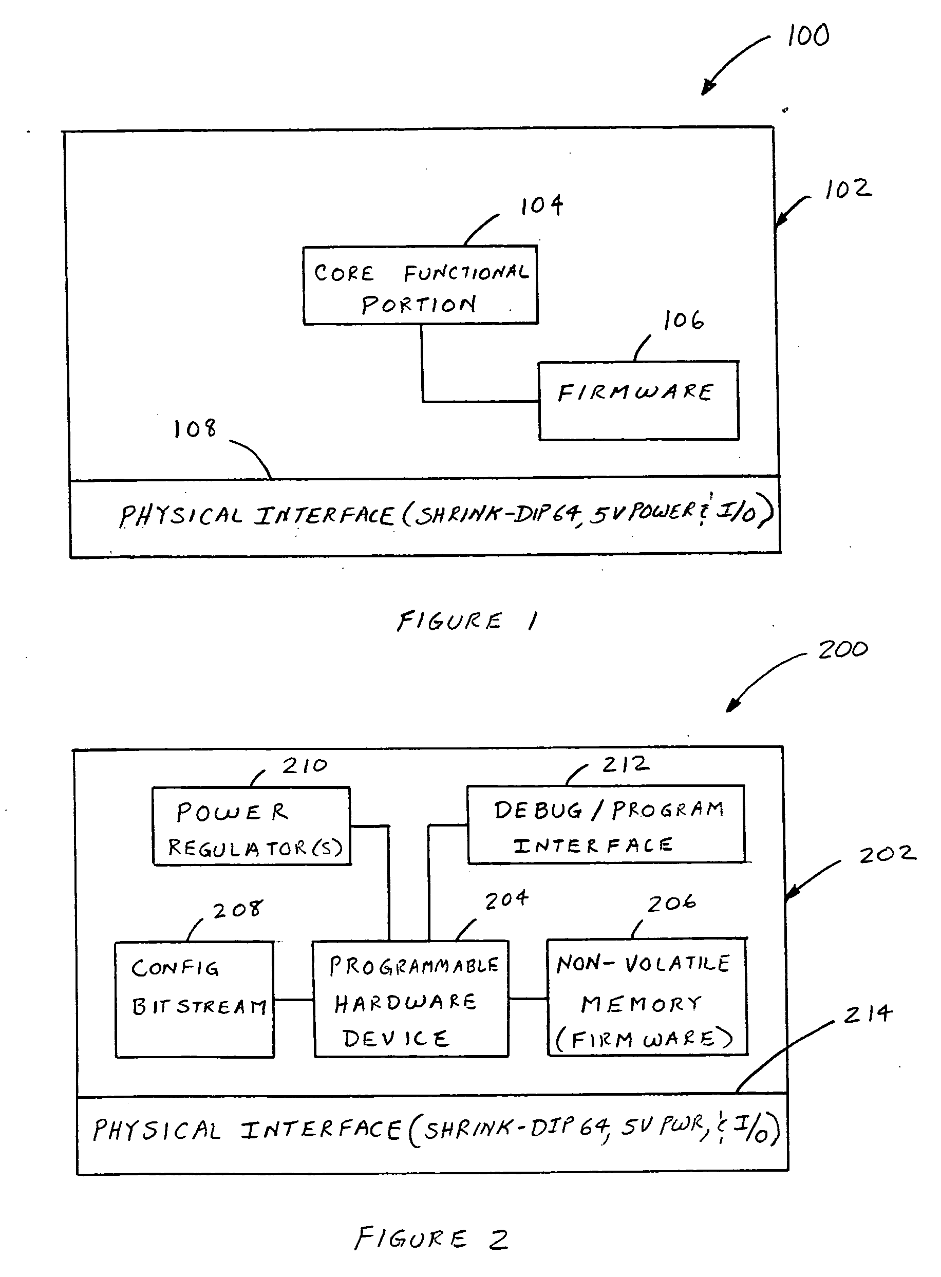
[0016]FIG. 1 illustrates a diagram of an existing microprocessor 100 of a vehicle system control unit of a particular vehicle-type. It shall be understood that the term “microprocessor” as used herein also includes microcontrollers, microcomputers, and other devices that execute software instructions. The existing microprocessor 100 is an example of a device that has become obsolete. In particular, the microprocessor 100 may include an integrated circuit 102 comprising a core functional portion 104, a firmware storage portion 106, and a physical interface 108. The core functional portion 104 performs the execution and processing of the software instructions. The firmware storage portion 106, which may be incorporated within the integrated circuit 102 or separate therefrom, stores instructions and data for initializing the core functional portion 104. The physical interface 108 serves as an interface for electrical connection to external components. The physical interface 108 may inc...


PUM


Abstract

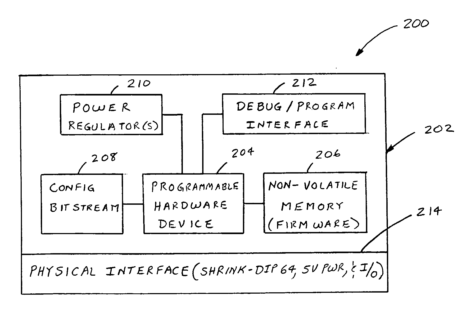
A method of dealing with a microprocessor used in a first vehicle system control unit becoming obsolete. The method comprises providing a second vehicle system control unit for performing substantially the same operation as that of the first vehicle system control unit, wherein the second vehicle system control unit includes a microprocessor emulation unit having a programmable hardware device adapted to emulate the operation of the core functional portion of the microprocessor. The programmable hardware device may comprise a field programmable gate array (FPGA) device, a field programmable logic device (FPLD), a programmable logic array (PLA), a mask programmable logic device (MPLD), a programmable array logic (PAL) device, or a complex programmable logic device (CPLD). The microprocessor emulation unit may include substantially the same firmware and physical interface of the obsolete microprocessor.

Description

FIELD OF THE INVENTION [0001] This invention relates generally to vehicle control systems, and in particular, to a system and method for addressing component obsolescence in microprocessor-based control units used in vehicle control systems. BACKGROUND OF THE INVENTION [0002] The development, production, and post-production lifetime of a vehicle-type can span a relatively long time from a technological view point. For example, the development phase of a vehicle-type may span, for example, four (4) years or more; the production phase of a vehicle-type may span, for example, seven (7) years or more; and the post-production phase of a vehicle-type (whereby spare parts are needed to continue servicing vehicles) may span, for example, up to 10 to 15 years. During such lengthy lifetime, the continued availability and supply of electronic components that make up the vehicle control system are required to meet the demands of the development, production, and post-production phases of the veh...

Claims


Application Information

Patent Timeline
IPC IPC(8): G06F9/455
CPCG06F11/2038G06F11/2028
Inventor ANANNY, JOHNKAINDL, MICHAEL
Owner BAYERISCHE MOTOREN WERKE AG
Learn More