Low complexity pseudo-random interleaver

a pseudo-random interleaver and low complexity technology, applied in the field of data communication channels, can solve the problems of high power consumption of the interleaver, the speed (, latency) of the interleaver, and the intensive focus of the interleaver

Inactive Publication Date: 2006-12-14
SEAGATE TECH LLC
View PDF40 Cites 88 Cited by
  • Summary
  • Abstract
  • Description
  • Claims
  • Application Information

AI Technical Summary

Problems solved by technology

The increasing demand for high data rate communications systems and high-density data storage devices has lead to intensive focus on implementation issues of iterative decoding concepts for error-correction codes (ECC's).
In designing interleavers (including deinterleavers), there are complex design tradeoffs between design parameters such as the degree of randomness of interleaving patterns, the area of silicon used to implement the interleaver, size of memories needed to support the interleaver, the power consumption of the interleaver and the speed (or conversely the latency) of the interleaver.

Method used


Image

  • Low complexity pseudo-random interleaver
  • Low complexity pseudo-random interleaver
  • Low complexity pseudo-random interleaver

Examples


Embodiment Construction

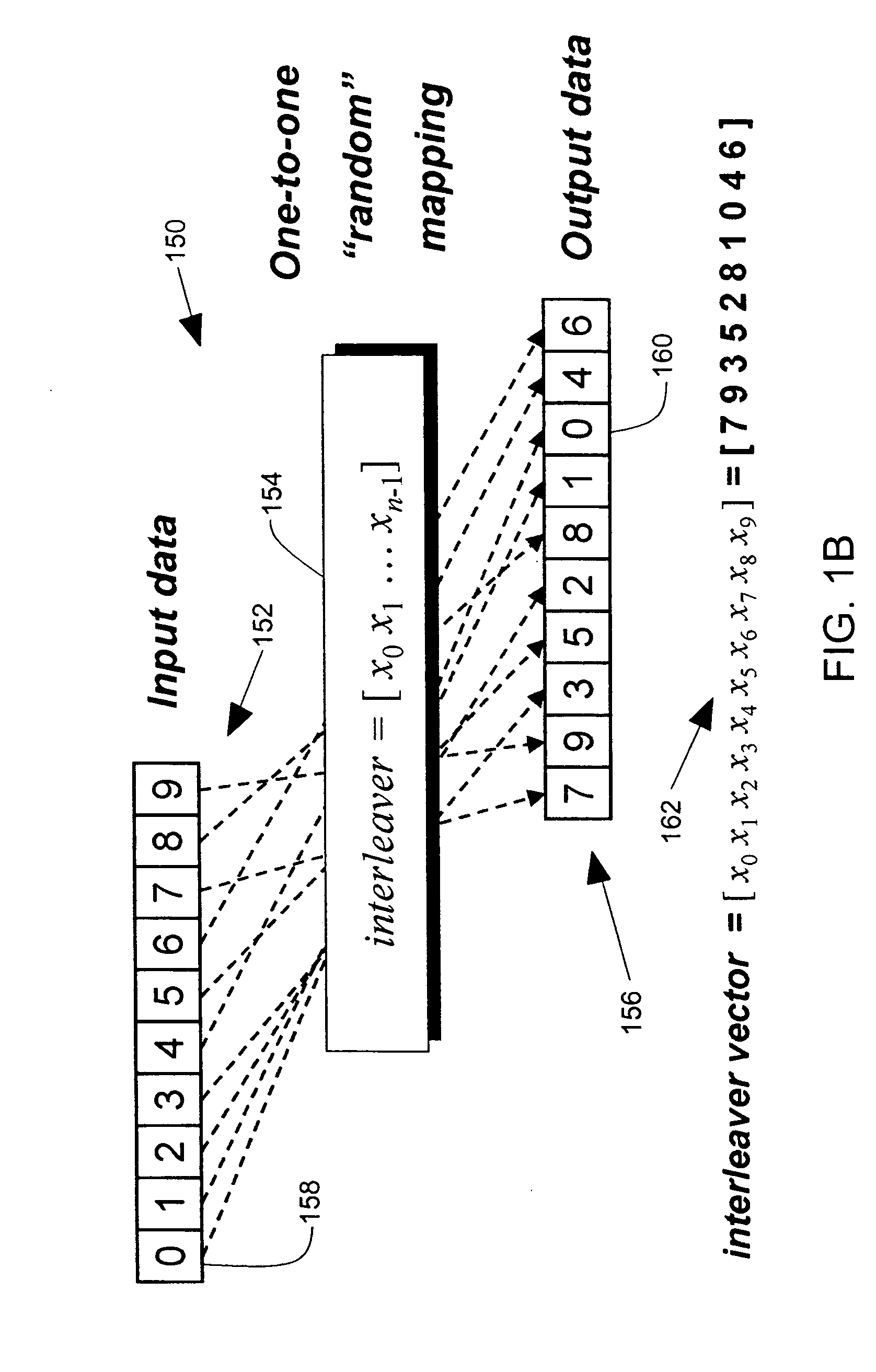
[0044] In the embodiments described below, a simple and yet efficient low-complexity interleaver combines a linear feedback shift register (LFSR), modulo-adder circuits, multiple-way interleaving, and toggling of address generators. The interleaver has an input multiplexer that separates an input data sequence (block) into multiple data sub-blocks. One or more linear feedback shift registers and adders are used to generate input and output address sequences for each sub-block. The interleaver has an output multiplexer that assembles the interleaved sequences to provide an interleaver output. The sub-blocks are smaller in length than the data block and sub-block processes can run slower without loss of overall speed for the block, reducing power consumption without loss of speed. The size of memories in the interleaver are smaller, reducing the area of silicon used and reducing power consumption.

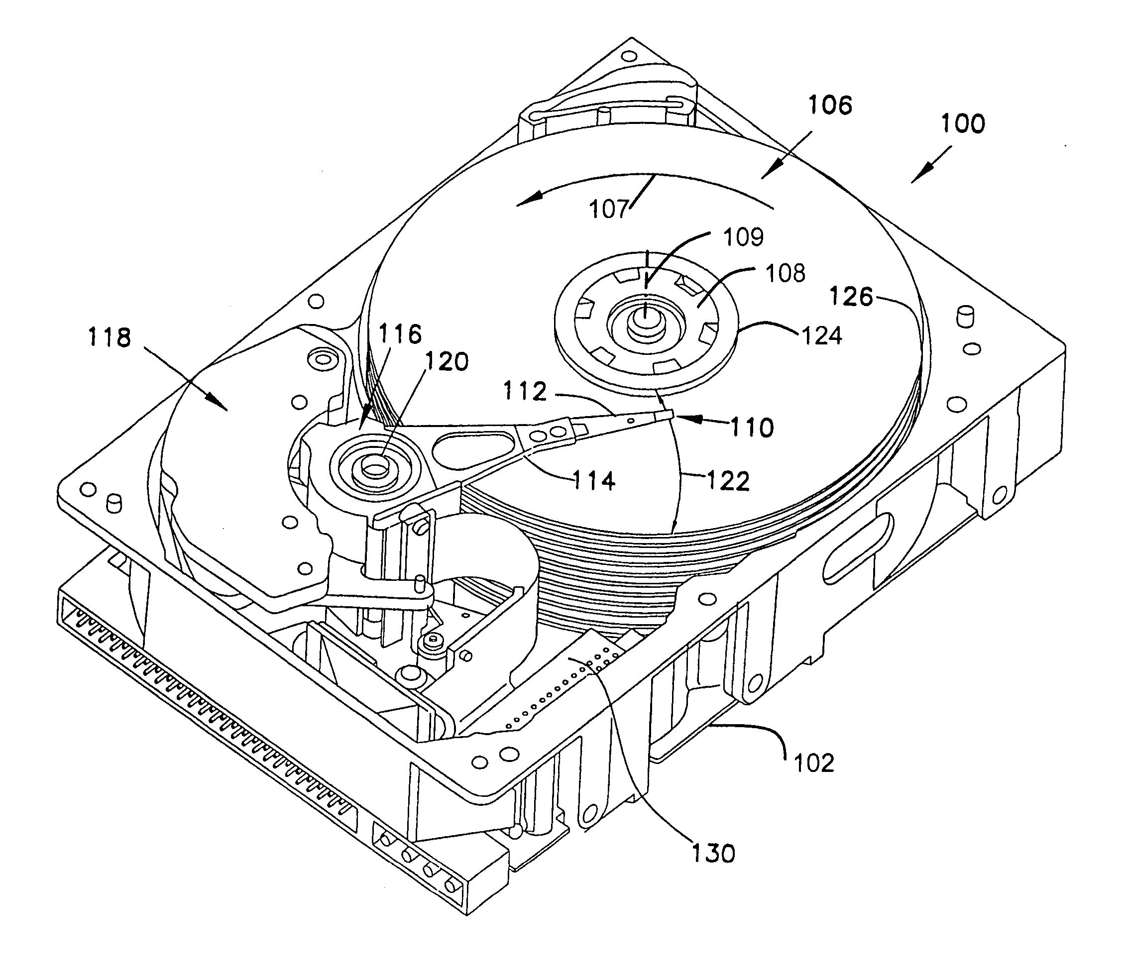
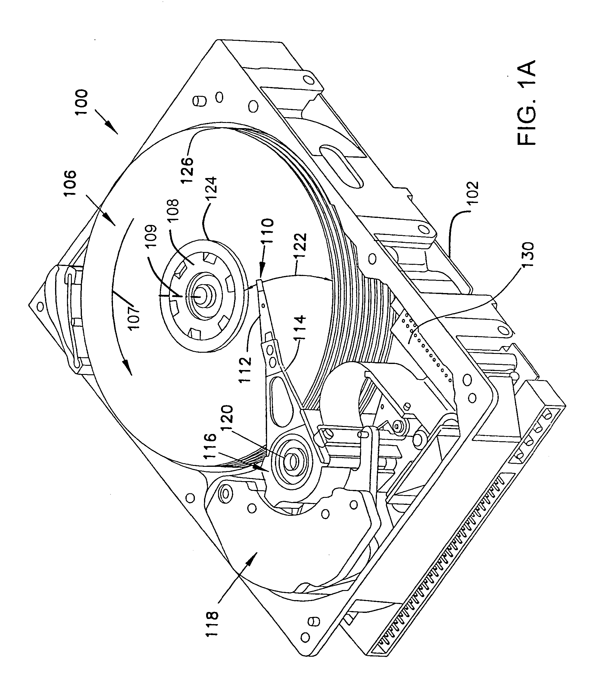
[0045]FIG. 1 is an isometric view of a disc drive 100 in which embodiments of the presen...


PUM


Abstract

An interleaver has an input multiplexer that receives a data sequence at an interleaver input and that separates the data sequence into multiple data sub-blocks. The interleaver has a linear feedback shift register that generates an input address sequence. The interleaver has adder circuits that generate output address sequences associated with each data sub-block. The interleaver has memory that stores the data sub-blocks at addresses controlled by the input address sequence. The memory reproduces each data sub-block in an interleaved sequence controlled by the associated output address sequence. The interleaver has an output multiplexer that assembles the interleaved sequences to provide an interleaver output.

Description

CROSS-REFERENCE TO RELATED APPLICATION [0001] Cross-reference is hereby made to U.S. application Ser. No. ______ entitled “Second Stage SOVA Detector” (Attorney Docket Number S01.12-1079 / STL12091 and to U.S. application Ser. No. ______ entitled “Iterative Detector with ECC in Channel Domain”) Attorney Docket Number S01.12-1078 / STL12265), which were filed on even date herewith. FIELD OF THE INVENTION [0002] The present invention relates generally to data communication channels, and more particularly but not by limitation to such channels in data storage devices. BACKGROUND OF THE INVENTION [0003] Data communication channels generally include encoding of data before it passes through a communication medium, and decoding of data after it has passed through a communication medium. Data encoding and decoding is used, for example, in data storage devices for encoding data that is written on a storage medium and decoding data that is read from a storage medium. Encoding is applied in order...

Claims


Application Information

Patent Timeline
Patent Type & Authority Applications(United States)
IPC IPC(8): G06F11/00
CPCH03M13/276H03M13/2742
Inventor ARGON, CENKBORN, RICHARD MARTINSILVUS, GREGORY LEESOUVIGNIER, THOMAS VICTORVASILIEV, PETER IGOREVICH
Owner SEAGATE TECH LLC
Why Eureka
Try Eureka