Wireless controller and application interface for an MRI system

a wireless controller and application interface technology, applied in the field of diagnostic imaging arts, can solve the problems of reducing image quality, introducing radio frequency (rf) disturbances into the imaging volume, patient unattended during the scan, etc., and achieve the effect of reducing cumbersome materials and improving mobility

Inactive Publication Date: 2005-11-01
KONINKLIJKE PHILIPS ELECTRONICS NV +1
View PDF15 Cites 45 Cited by
  • Summary
  • Abstract
  • Description
  • Claims
  • Application Information

AI Technical Summary

Benefits of technology

[0010]One advantage of the present invention resides in improved mobility for patients and operators around an MR device.
[0011]Another advantage resides in the ability of the operator to remain close to the patient during the scan.
[0012]Another advantage resides in the reduction of cumbersome material within the medical ima

Problems solved by technology

This typically leaves the patient unattended during the scan.
In many patients, being alone and in such a constricted area such as the bore of an MR device can cause increased anxiety and restlessness, ultimately degrading image quality.
Cables typically present a problem in that they can introduce radio frequency (RF) disturbances into the imaging volume and receive ambient RF signals.
Ultimately, these RF disturbances manifest as imaging artifacts in final images.
As a result of

Method used


Image

  • Wireless controller and application interface for an MRI system
  • Wireless controller and application interface for an MRI system
  • Wireless controller and application interface for an MRI system

Examples


Embodiment Construction

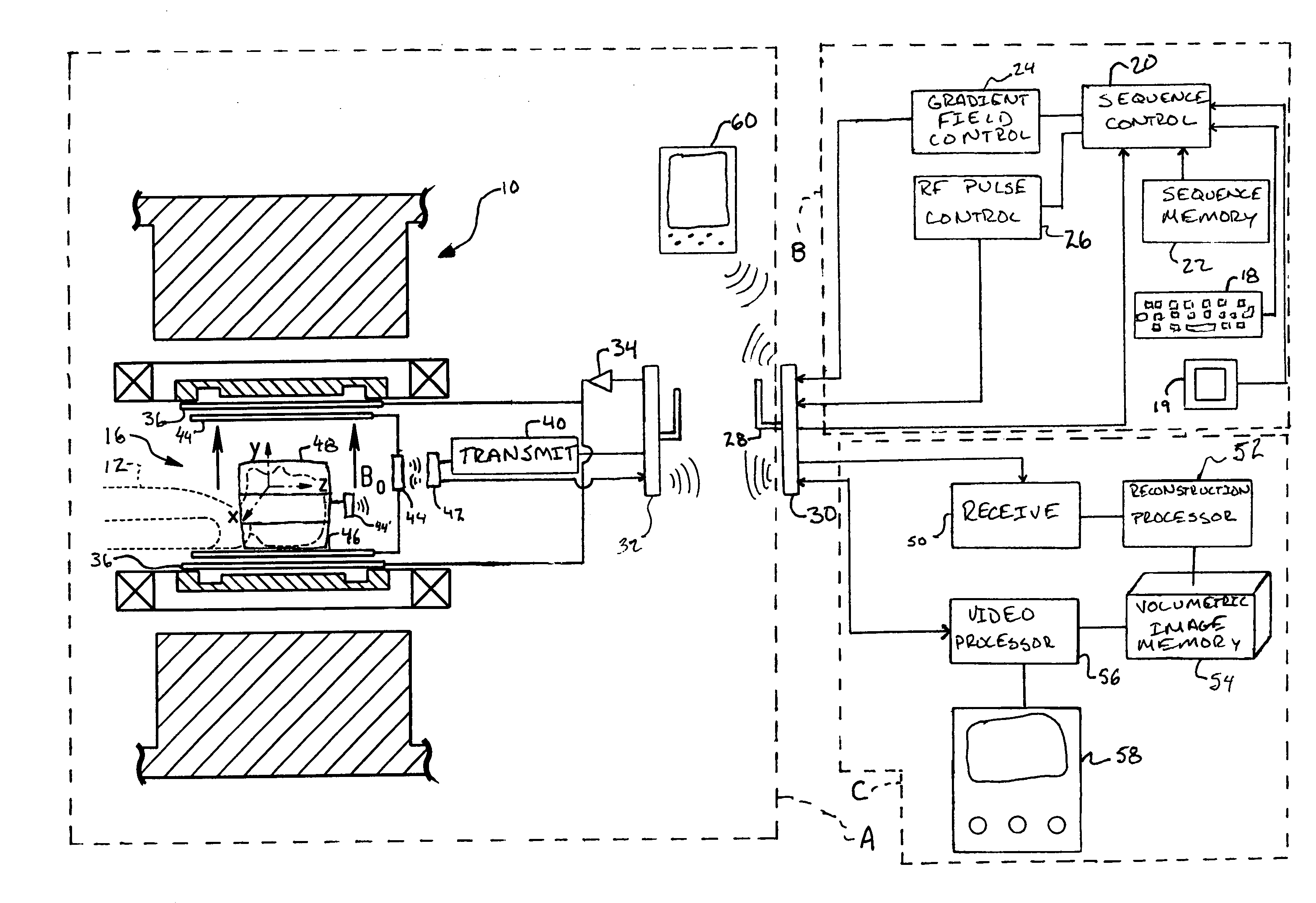
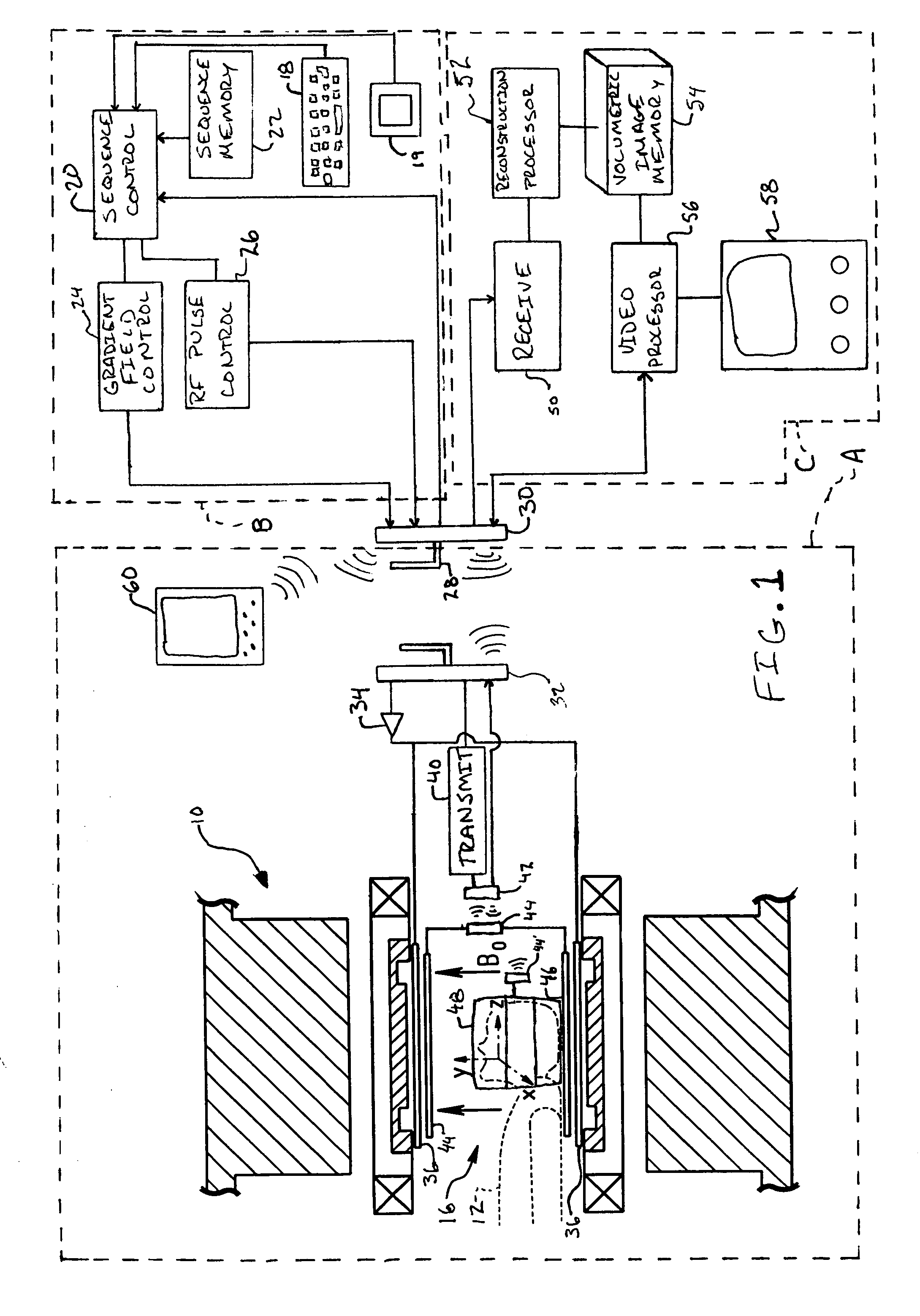
[0018]With reference to FIG. 1, an open main magnet assembly 10 which generates a temporally constant main magnetic field, typically denoted Bo, vertically through an imaging region 16 is disposed in a magnetic resonance suite A. It should be noted that although depicted in conjunction with an open magnet system, the preferred embodiment of the present invention is equally applicable to bore type systems. A subject 12 is disposed on a patient support located in the imaging region 16 of the magnet assembly 10. The main magnet assembly, 10 is located within a magnetic resonance suite, which is preferably shielded to be impervious to electromagnetic radiation, particularly in the radio frequency band.

[0019]A sequence control system B generates magnetic resonance imaging sequences. A keyboard 18 or touch screen 19 receives operator control commands. A sequence control processor 20 withdraws a selected magnetic resonance sequence from a sequence memory 22. A gradient field controller 24 ...


PUM


Abstract

A wireless remote control unit (60) that operates in the radio frequency bandwidth is used for interfacing with a sequence control system (B) and an image processing system (C) from within a magnetic resonance suite (A) in the presence of a magnetic field produced by a main magnet assembly (10). The sequence control system and the image processing system are connected with a first wireless transceiver (30) whose antenna (28) is located within a magnetic resonance suite. The first transceiver (30) communicates with the remote control unit (60) and a second transceiver (32) connected with a transmitter (40) and gradient coil amplifiers (34). Resonance signals received by a radio frequency coil (46) are communicated to the first transceiver (30) by the second transceiver (32) or by a transceiver (46′) mounted on the receiving coil. The receiver coil transceiver also engages in a handshake protocol to identify itself.

Description

BACKGROUND OF THE INVENTION[0001]The present invention relates to the diagnostic imaging arts. It has particular application in conjunction with wireless communication in a magnetic resonance setting and will be described with particular reference thereto. It will be appreciated, however, that the invention is also applicable to other modalities including, but not limited to, CT, SPECT, and PET.[0002]Magnetic resonance (MR) imagers generate high magnetic fields through an imaging region. A typical by-product of the production of this field is a magnetic fringe field that can extend several meters beyond the physical apparatus. Although the excitation fields are high, the induced resonance signals are weak comparable with ambient television and radio signals. In order to minimize disruption to and interference from the surroundings in an environment such as a hospital or clinic, the magnets are often built within specially shielded suites to prevent the fringe field from affecting su...

Claims


Application Information

Patent Timeline
IPC IPC(8): G01R33/28A61B5/055G01R33/48H04Q9/00
CPCG01R33/283G01R33/3692
Inventor VAHASALO, SEPPO T.EHNHOLM, GOSTA J.
Owner KONINKLIJKE PHILIPS ELECTRONICS NV
Why Eureka
Try Eureka