
Oxygen concentrating apparatus and rotary valve

a technology of concentrating apparatus and rotary valve, which is applied in the direction of mechanical apparatus, multiple way valves, separation processes, etc., can solve the problems of unbalance in the pressure applied to the interface between the rotor and the stator of the rotary valve, and achieve the effect of increasing the pressur

Inactive Publication Date: 2006-12-21
TEIJIN PHARMA CO LTD
View PDF11 Cites 35 Cited by
  • Summary
  • Abstract
  • Description
  • Claims
  • Application Information

AI Technical Summary

Benefits of technology

[0023] (5) increasing the pressure in said one of the adsorption cylinders by directing the oxygen enriched gas into said

Problems solved by technology

However, the conventional rotary valve has a problem that there is unbalance in the pressure applied to the interface between the rotor and the stator of the rotary valve.

Method used


Image

  • Oxygen concentrating apparatus and rotary valve
  • Oxygen concentrating apparatus and rotary valve
  • Oxygen concentrating apparatus and rotary valve

Examples


first embodiment

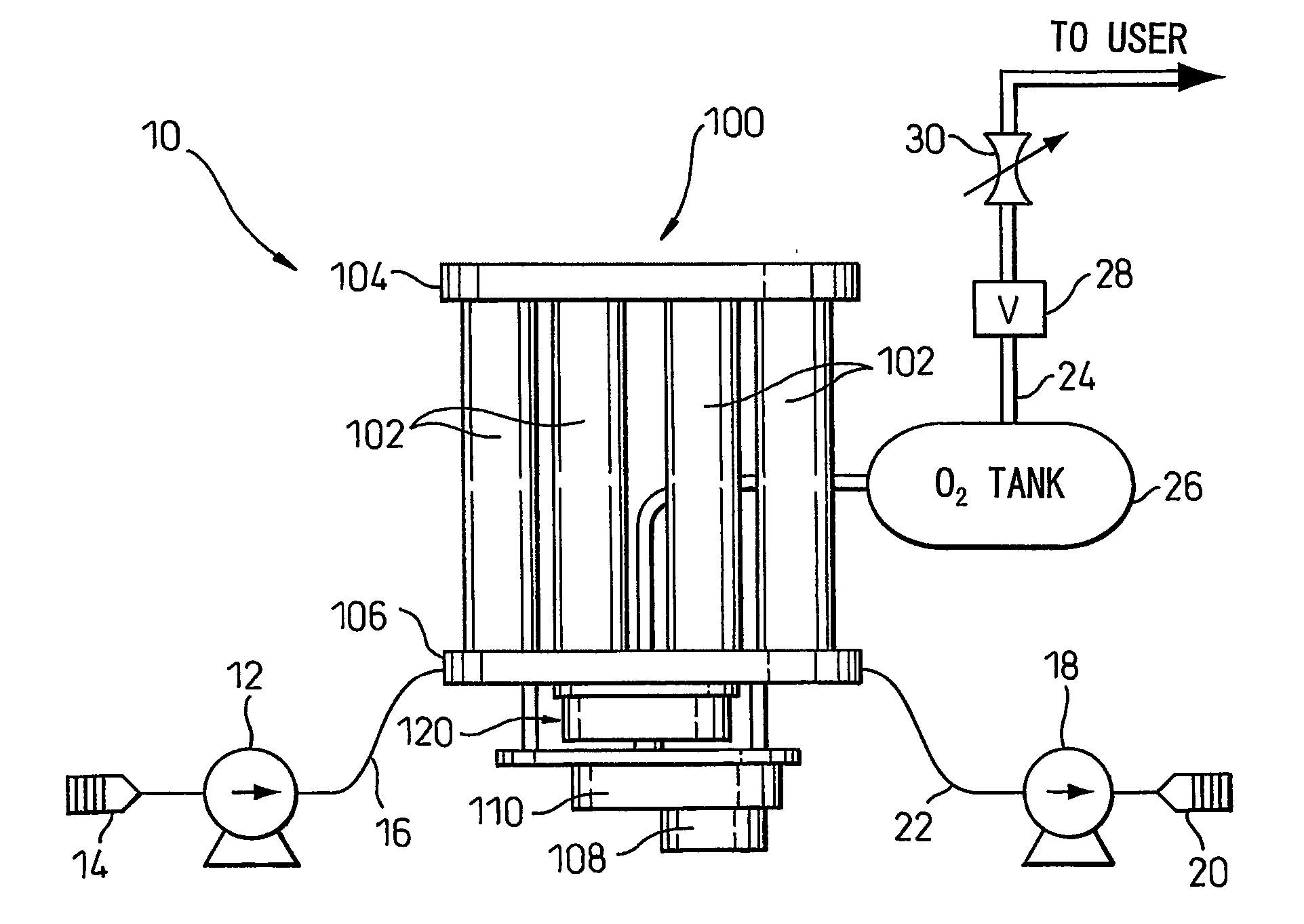
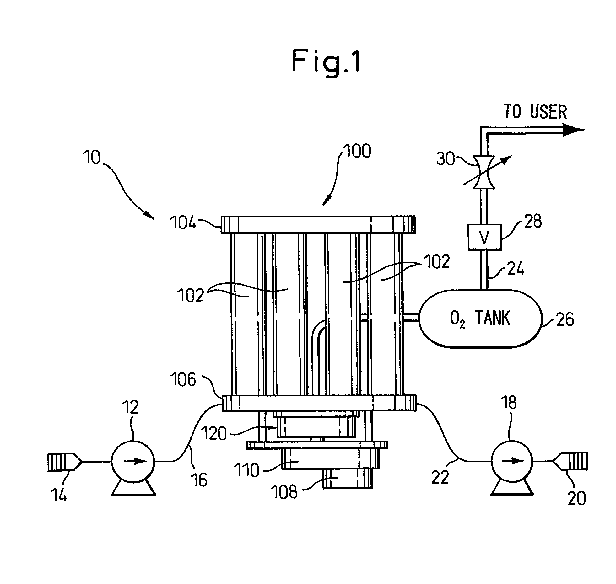
[0056] In FIG. 1, an oxygen concentrating apparatus according to the present invention is shown. The oxygen concentrating apparatus 10 has an oxygen concentrator 100 which generates an oxygen enriched gas by adsorbing and separating nitrogen gas from the air, an air supplying means, comprising a compressor 12 and a filter 14, for supplying compressed air to the oxygen concentrator 100 through an air supply conduit 16, an exhausting means, comprising a vacuum pump 18 and a muffler 20, for drawing nitrogen gas through exhaust conduit 22, a reservoir or an O2 tank 26, a pressure regulating valve 28, a flow control valve 30 which are disposed along an oxygen supply conduit 24 for directing the oxygen enriched gas to a user.

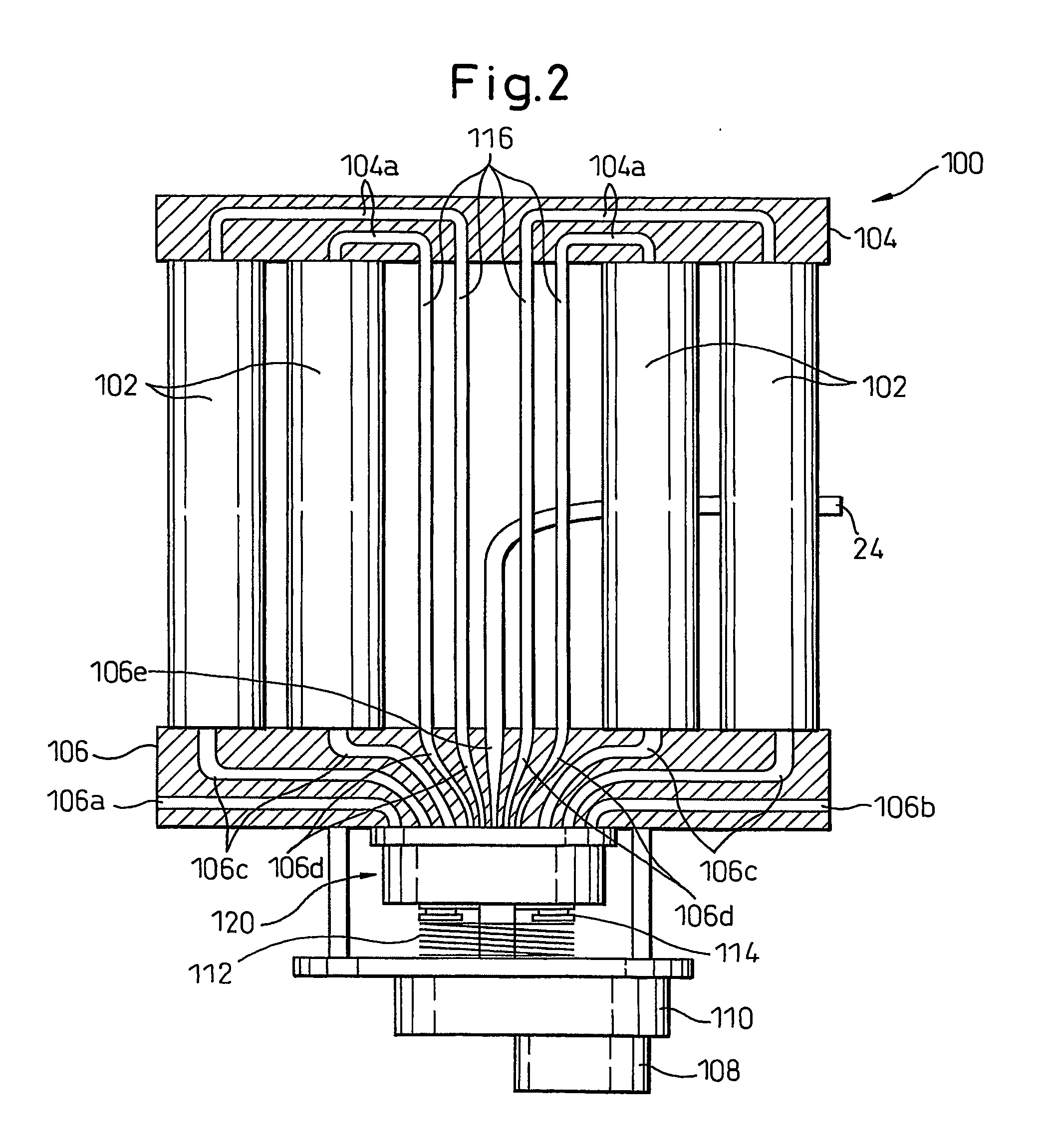
[0057] With reference to FIG. 2, the oxygen concentrator 100 includes a plurality of adsorption cylinders 102 which are arranged parallel to each other and filled with an adsorbent, for example, zeolite for selectively adsorbing nitrogen gas more than oxygen gas, uppe...

second embodiment

[0081] With reference to FIGS. 16-28, the present invention will be described below.

[0082] The oxygen concentrator 200 according to the second embodiment includes a plurality of adsorption cylinders 202 which are arranged parallel to each other and filled with an adsorbent, for example, zeolite which selectively adsorbs nitrogen gas more than oxygen gas, upper and lower headers 204 and 206 holding the adsorption cylinders 202 therebetween, a rotary valve 220 and drive mechanism, comprising a motor 208 and gear box 210, for rotating the rotary valve 220, a spring 212 for biasing a cover of the rotary valve 220 and a bearing 214, between the spring 212 and the rotary valve 220, which allows the rotary valve 220 to rotate.

[0083] The oxygen concentrator 200 has six adsorption cylinders 202 each of which includes a top or first orifice (not shown) and a bottom or second orifice (not shown). The upper header 204 includes six passages 204a which are fluidly connected to the upper orifices...


PUM


Abstract

According the present invention, an oxygen enriched gas is generated by adsorbing and removing nitrogen gas from air with an oxygen concentrating apparatus which conducts the steps of (1) pressurizing one of the adsorption cylinders by directing the compressed air; (2) removing the oxygen enriched gas from said one of the adsorption cylinders to the output conduit; (3) reducing the pressure in said one of the adsorption cylinders by directing the oxygen enriched gas into one of the other adsorption cylinders to increase the pressure in the one of the other adsorption cylinders; (4) evacuating the internal gas out of said one of the adsorption cylinders; and (5) increasing the pressure in said one of the adsorption cylinders by directing the oxygen enriched gas into said one of the adsorption cylinders from one of the other adsorption cylinders in which the pressure is decreased in step (3).

Description

BACKGROUND OF THE INVENTION [0001] 1. Field of the Invention [0002] The present invention relates to an oxygen concentrating apparatus and a rotary valve. [0003] 2. Description of the Related Art [0004]FIG. 29 is a schematic illustration of a pressure swing type gas oxygen concentrating apparatus 300 which includes two adsorption cylinders 302a and 302b,an air compressor 304 for supplying compressed air to the adsorption cylinders 302a and 302b through conduit 308, four-way directional control valve 306, conduits 310a and 310b, an O2 tank 320 to which the oxygen enriched gas is supplied from the adsorption cylinders 302a and 302b through output conduits 312a and 312b and shut off valves 318. The oxygen enriched gas is supplied from the O2 tank to a user through a conduit 322 and a flow control valve 324. Provided between the output conduits 312a and 312b are a orifice 314 and a pressure equalizing valve 316. [0005] According to the oxygen concentrating apparatus 300, it is difficult...

Claims


Application Information

Patent Timeline
IPC IPC(8): B01D53/02B01D53/047F16K11/074
CPCB01D53/047F16K11/074B01D2256/12B01D2257/102B01D2259/40005B01D2259/40022B01D2259/4003B01D2259/40037B01D2259/40041B01D2259/40069B01D2259/40075B01D2259/404B01D2259/4062B01D2259/4533B01D2253/108B01D53/02B01D53/54
Inventor SUGANO, MASATO
Owner TEIJIN PHARMA CO LTD
Features
  • Generate Ideas
  • Intellectual Property
  • Life Sciences
  • Materials
  • Tech Scout
  • Unparalleled Data Quality
  • Higher Quality Content
  • 60% Fewer Hallucinations
Learn More