Fluid driven drilling motor and system

a technology of fluid-driven drilling motors and motors, which is applied in the direction of drilling accessories, earth-moving drilling and mining, and wellbore/well accessories. it can solve the problems of reducing the efficiency of drilling, reducing the torque of the motor and slow boring, and no prior art apparatus and methods minimize the pressure loss of the drilling fluid. , to achieve the effect of increasing the overall torque, increasing the hydraulic pressure and increasing the drilling efficiency

Inactive Publication Date: 2006-12-21
BOW RIVER TOOLS & SERVICES
View PDF19 Cites 30 Cited by
  • Summary
  • Abstract
  • Description
  • Claims
  • Application Information

AI Technical Summary

Benefits of technology

[0011] At least one, and preferably two or more ramped apertures are formed in the side wall of the cylindrical flow collar. Each ramped aperture includes an inlet on an outer surface of the sidewall and a corresponding opening within the cylindrical flow collar such that the drilling fluid may be directed to the bore in the second end of the flow collar. The ramped apertures are therefore in fluid communication with the bore such that the drilling fluid may enter the bore via the inlets and the openings. Each of the ramped apertures include inclined ramp surfaces and inclined side surfaces extending radially, relative to a longitudinal axis of the bore, between the inlets and the corresponding openings. The ramped surfaces and side ramp surfaces are formed such that drilling fluid flowing under pressure down past the flex shaft may be directed and drawn into the ramped apertures along a fluid flow path which spirals downwardly and radially inwardly of the flow collar so as to then flow into the bore. The pressure loss associated with drawing the drilling fluid into the ramped apertures is thereby minimized such that increased hydraulic pressure is available to increase the overall torque and hydraulic power of the drill motor to increase drilling efficiency.
[0012] In an embodiment of the invention, the cylindrical flow collar includes a shear pin positionabile and mountable between the flex shaft and the drive shaft such that the shear pin may shear in the event of excess torsional stress, thereby inhibiting breakage of the drive shaft.

Problems solved by technology

As the drilling fluid is pumped down the drill string and through the mud motor, pressure loss due to friction reduces the amount of pressure supplied to the motor, causing a decrease in motor torque and slower boring.
Further pressure loss at the motor due to narrow flow passages also reduces the efficiency of drilling.
However, none of the prior art apparatus and methods minimize the pressure loss of the drilling fluid in the manner of the present invention.

Method used


Image

  • Fluid driven drilling motor and system
  • Fluid driven drilling motor and system
  • Fluid driven drilling motor and system

Examples


Embodiment Construction

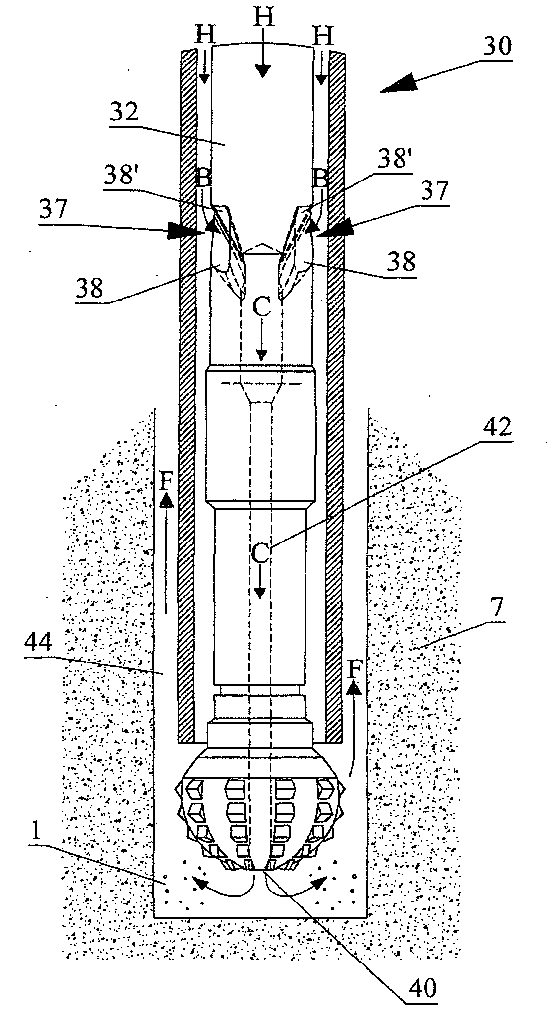
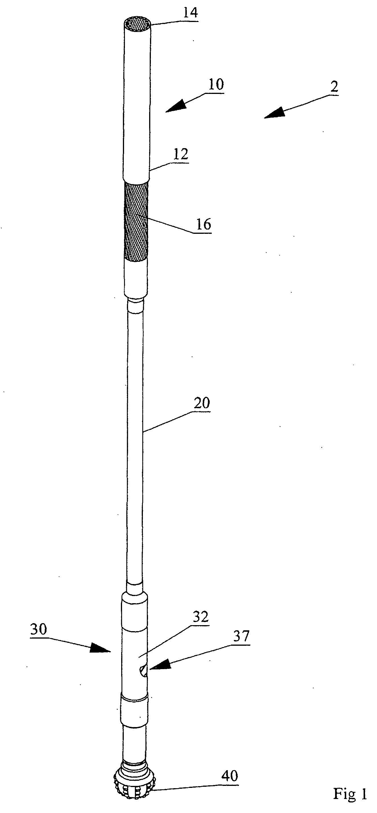
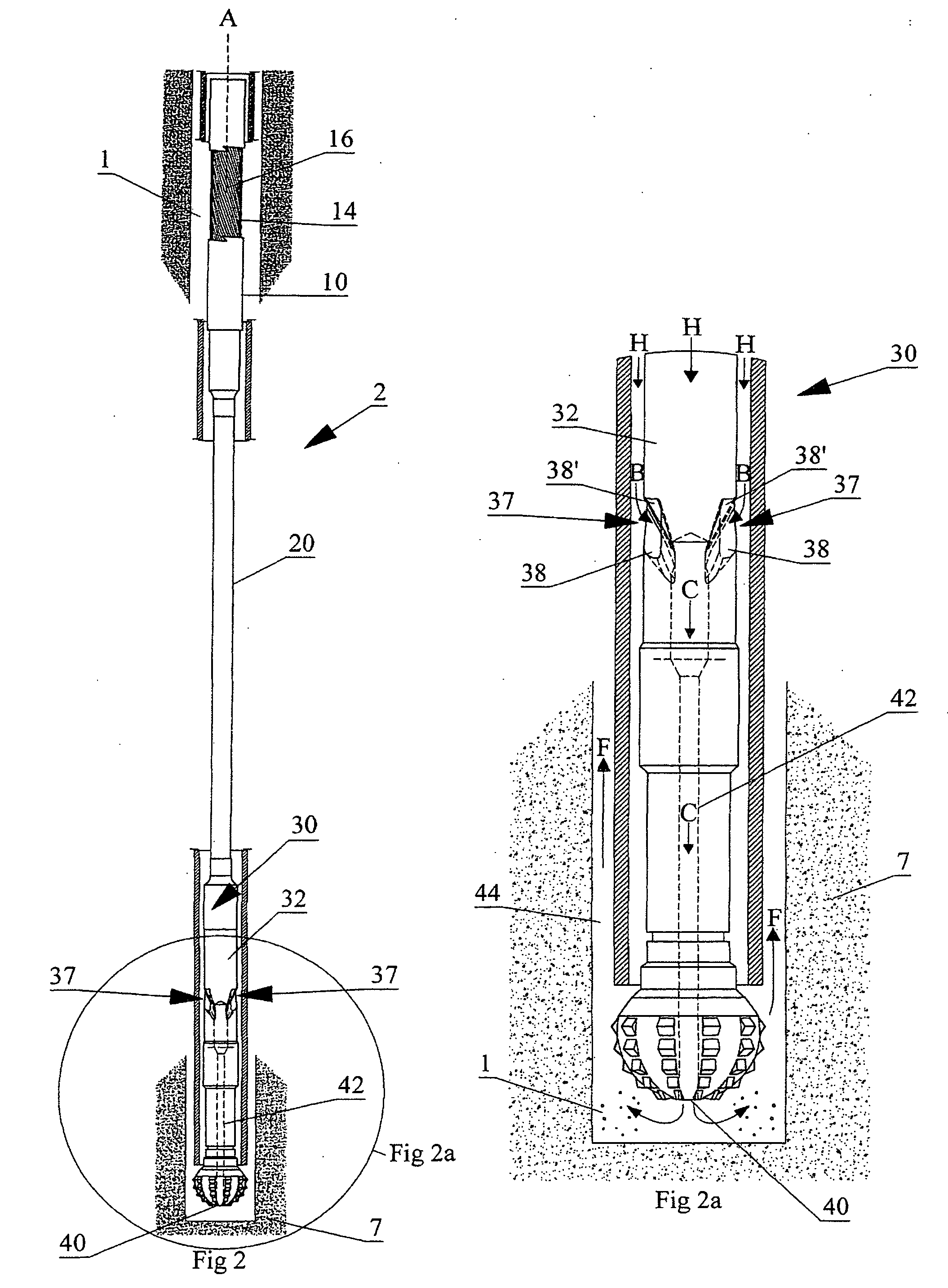
[0021] With reference to the FIGS. 1 to 5 wherein similar characters of reference denote corresponding parts in each view, the fluid driven drilling system according to the present invention includes a drill string 2 having a power section 10, a flex shaft 20, a flow collar 30, and a drill bit 40 coaxially mountable to each other. Power section 10, which includes a down-hole drilling motor 12, is coaxially mounted within a drill pipe (shown in FIG. 2) to flex shaft 20. Flex shaft 20 is coaxially mounted between power section 10 and flow collar 30. Down-hole drilling motor 12 is mounted to an upper end of flex shaft 20. Flow collar 30 is mounted to an opposite lower end of flex shaft 20. Flow collar 30 is mounted between flex shaft 20 and drill bit 40. An upper end of flow collar 30 is mounted to flex shaft 20. Alternatively, flow collar 30 may form the lower end of flex shaft 20, as described below. The lower end of flow collar 30 is configured to coaxially receive drill bit 40. Dri...


PUM


Abstract

A fluid driven drilling motor and system includes a flex shaft between the rotor and a cylindrical flow collar. The end of the flow collar opposite from the flex shaft has a bore in fluid communication with a drill bit. Ramped apertures are formed in the side wall of the flow collar. The ramped apertures are in fluid communication with the bore. Drilling fluid flowing under pressure down past the flex shaft is directed and drawn into the ramped apertures along a fluid flow path which spirals downwardly and radially inwardly of the flow collar so as to then flow into the bore. The pressure loss associated with drawing the drilling fluid down to the drill bit is thereby minimized.

Description

CROSS REFERENCE TO RELATED APPLICATION [0001] This application claims priority from U.S. Provisional Patent Application No. 60 / 692,265 filed Jun. 21, 2005 entitled Fluid Driven Drilling Motor and System.FIELD OF THE INVENTION [0002] The present invention relates to the field of drilling systems, and more particularly, it relates to an improved mud motor. BACKGROUND OF THE INVENTION [0003] Conventional rotary drilling operations rotate the drill bit by turning the entire drill string at the surface with a rotary table and kelly. However, a down-hole motor, such as a down-hole mud motor, utilizes the circulation system and the hydraulic power of a drilling fluid to rotate the drill bit without rotating the entire drill string within the well bore. A down-hole mud motor system may include drill collars which are larger diameter pipes attached to the drill pipe at a lower end of the drill string above the drill bit wherein the drill collar helps to add weight to the drill string to ensu...

Claims


Application Information

Patent Timeline
Patent Type & Authority Applications(United States)
IPC IPC(8): E21B4/02
CPCE21B4/02
Inventor REAGAN, LOREN PETER
Owner BOW RIVER TOOLS & SERVICES
Why Eureka
Try Eureka