

Biosignal detection device
a detection device and biosignal technology, applied in the direction of person identification, instruments, tractors, etc., can solve the problems of poor availability and usability, inability to detect heart rate signals or the like, and inability to eliminate noise elements, so as to achieve the effect of effective detection of biological information
- Summary
- Abstract
- Description
- Claims
- Application Information
AI Technical Summary
Benefits of technology
Problems solved by technology
Method used
Image

Examples
first embodiment
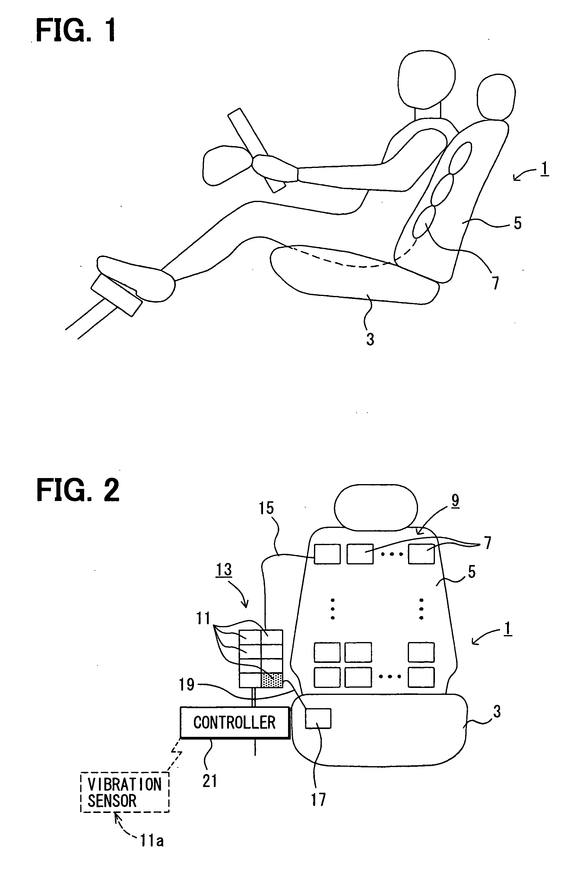
[0029] A biosignal detection device according to a first embodiment detects biological information, for example, a heart rate of a driver sitting on a driver's seat or the like, and assesses the driver's drowsiness and / or stress on the basis of the biological information.
[0030] First, system configuration of the biosignal detection device of the present embodiment will be described below.
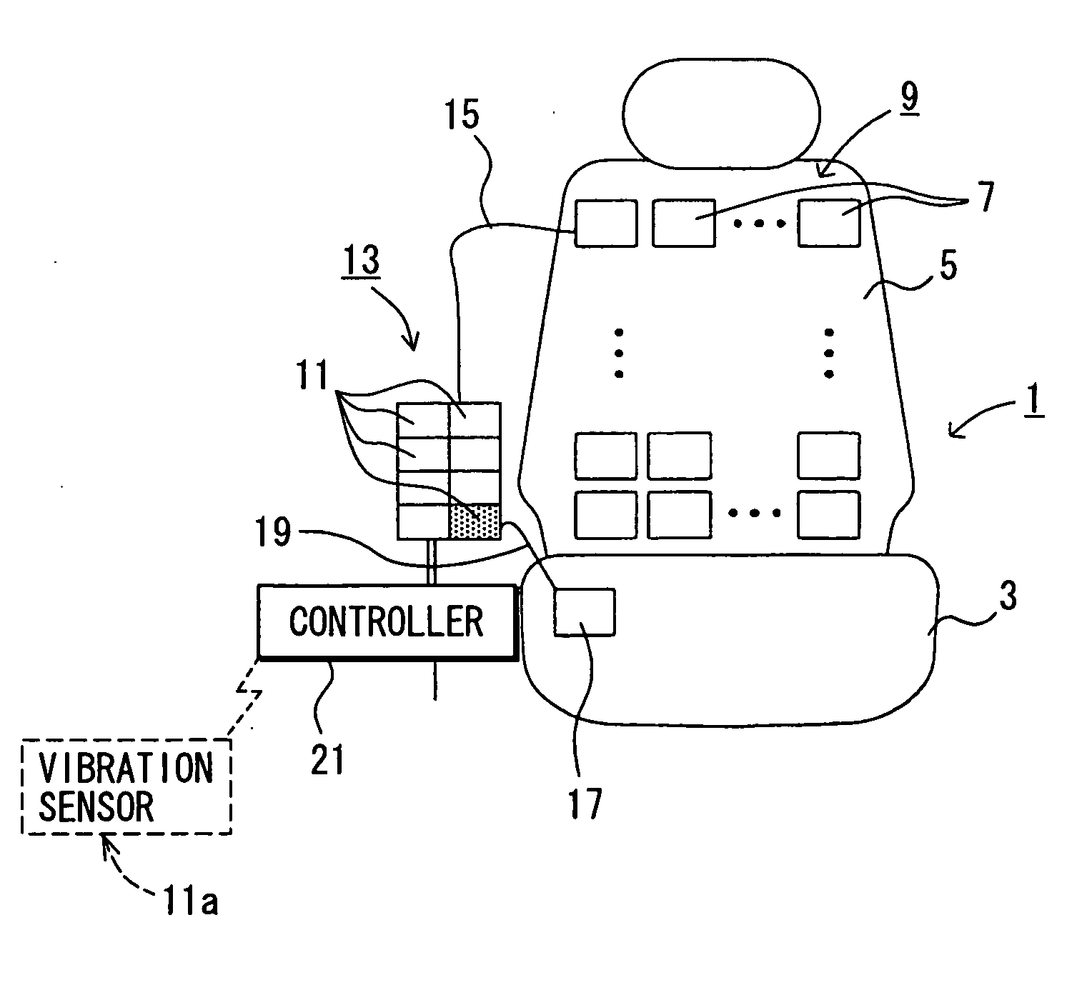
[0031] As shown in FIG. 1, a driver's seat 1 includes a seating face portion 3 on which the driver sits and a backrest portion 5 that supports the driver's back. The biosignal detection device of the present embodiment is disposed mainly in the driver's seat 1.
[0032] A plurality of bags that include air (i.e., detection air bags 7) is placed in the backrest portion 5 of the driver's seat 1. More specifically, the detection air bags 7 are arrayed in a grid pattern both along and all over a surface of the backrest portion 5 to form a back array 9 including air as shown in FIG. 2. This arrangement a...
second embodiment
[0062] The second embodiment will be described below, although description, which is similar to that of the first embodiment, is omitted. Since the present embodiment involves a different process from what is described in the first embodiment, content of the process will be described below.
[0063] A process of calculating pulse wave propagation velocity PWV that is employed for a process in the present embodiment will be described below. The pulse wave propagation velocity PWV is defined here as average velocity while a pulse wave is propagating and varies between individuals.
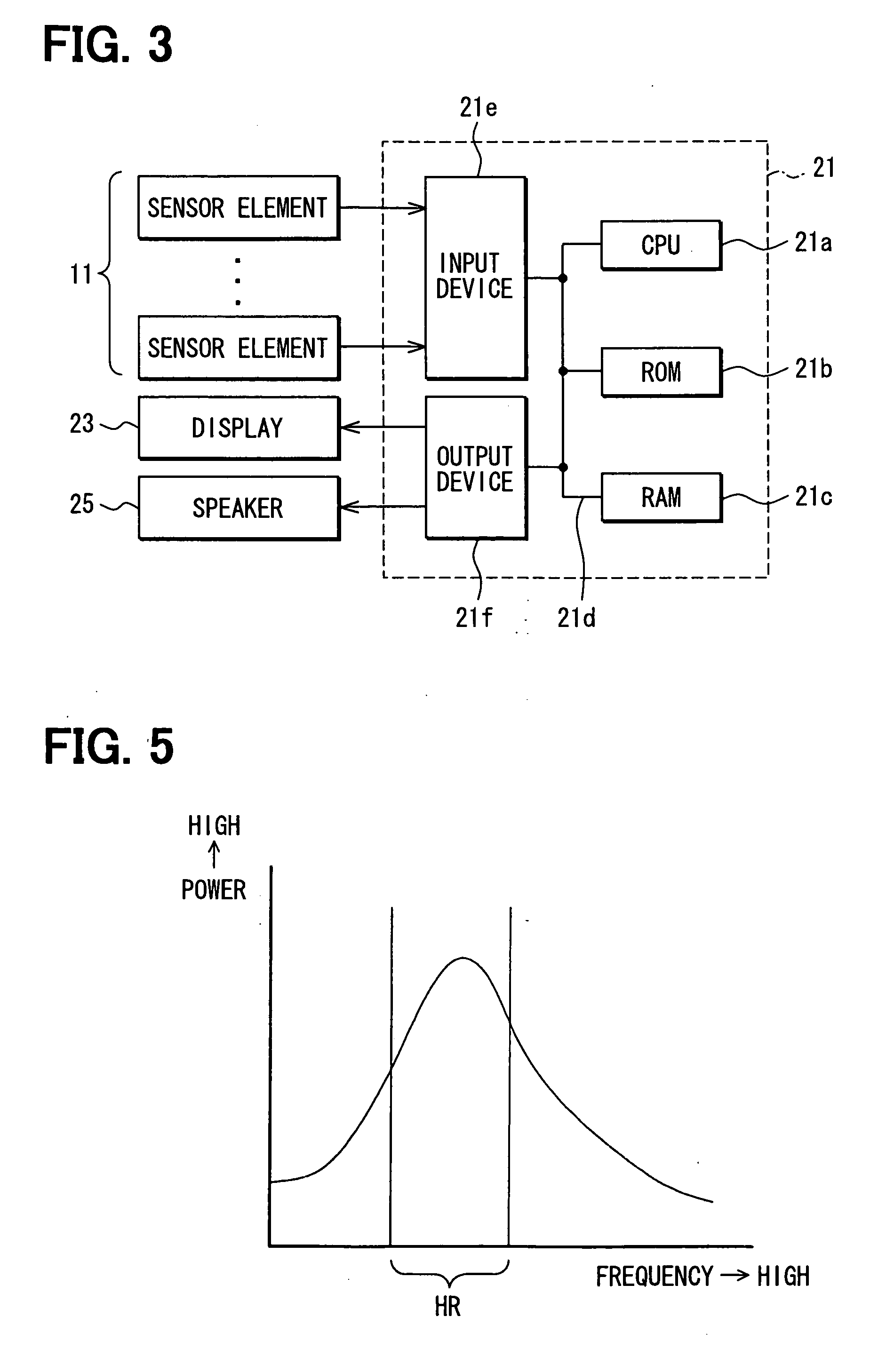
[0064] In order to detect the pulse wave propagation velocity PWV [m / s] when vehicle vibration is the smallest, for example, when a vehicle idles, the frequency analysis is performed on the sensor output of each pressure sensor by means of FFT at step 200 as shown in a flowchart in FIG. 8.
[0065] The power spectra of each sensor signal are derived from results of the frequency analysis. A pressure sensor, a po...
third embodiment
[0100] The third embodiment will be described below, although description, which is similar to that of the first embodiment, is omitted.
[0101] Similar to the first embodiment, in a backrest portion 43 of a driver's seat 41, a plurality of detection air bags 45 are arrayed in a grid pattern as shown in FIG. 12.
[0102] A sensor array 49 aside of the driver's seat 41 includes sensor elements 47 that are arrayed in a grid pattern. Via an air tube 51, each detection air bag 45 is connected to each sensor element 47 in such a manner that the detection air bag 45 and the sensor element 47 correspond one-to-one to each other. In addition, reference air bags 55 similar to those in the first embodiment are arrayed in a seating face portion 53
[0103] In the present embodiment particularly, a pressure valve 57 is inserted in an air tube 51 that connects each detection air bag 45 to the corresponding sensor element 47.
[0104] By opening under certain conditions, for example, when pressure applie...
PUM
 Abstract
Description
Claims
Application Information