Biological information measuring module and biological information measuring apparatus

Inactive Publication Date: 2016-07-07
SEIKO EPSON CORP
View PDF2 Cites 6 Cited by
  • Summary
  • Abstract
  • Description
  • Claims
  • Application Information

AI Technical Summary

Benefits of technology

[0053]According to this application example, detection (measurement) can be performed more accurately, and the biological information measuring module having a small size and excellent portab

Problems solved by technology

For example, when the light receiving unit and the light emitting unit become larger to a certain degree, the accuracy of measurement deteriorates.
On the other hand, when the light receiving unit and the light emitting unit become excessively larger, the apparatus becomes larger, which results in a problem of portability deterioration such as a burden to wearing a unit around an arm (wrist).
However, in the arm mounted measuring apparatus disclosed in JP-A-2000-254105, there is no description regarding the size of the optical pulse wave detection sensor (dimensions pertaining to the light emitting unit and the light receiving unit), and a problem in a configuration of a dimensional relationship between the above-mentioned light emitting unit and light receiving unit is not mentioned.
According to the biological information measuring module, when the circumference length of the light emitting unit on the outer circumference becomes smaller than 1.9 mm, light emission intensity is insufficient, and thus the light intensity of the reflected light, received by the light receiving unit, which is necessary for detection cannot be secured, which results in a deterioration in the measurement accuracy of biological information.
In addition, when the circumference length of the light emitting unit on the outer circumference exceeds 9.5 mm, an installation space for the light emitting unit becomes larger, and the biological information measuring module or a biological information measuring apparatus mounted with the biological information measuring module becomes larger accordingly, which may degrade portability.
According to the biological information measuring module, when the circumference length of the light receiving unit on the outer circumference becomes smaller than 5.3 mm, a light receiving region becomes excessively narrow, and thus it is not possible to sufficiently receive light necessary for detection, which resu

Method used


Image

  • Biological information measuring module and biological information measuring apparatus
  • Biological information measuring module and biological information measuring apparatus
  • Biological information measuring module and biological information measuring apparatus

Examples


Example

First Embodiment

1. Overall Configuration Example of Biological Information Measuring Apparatus

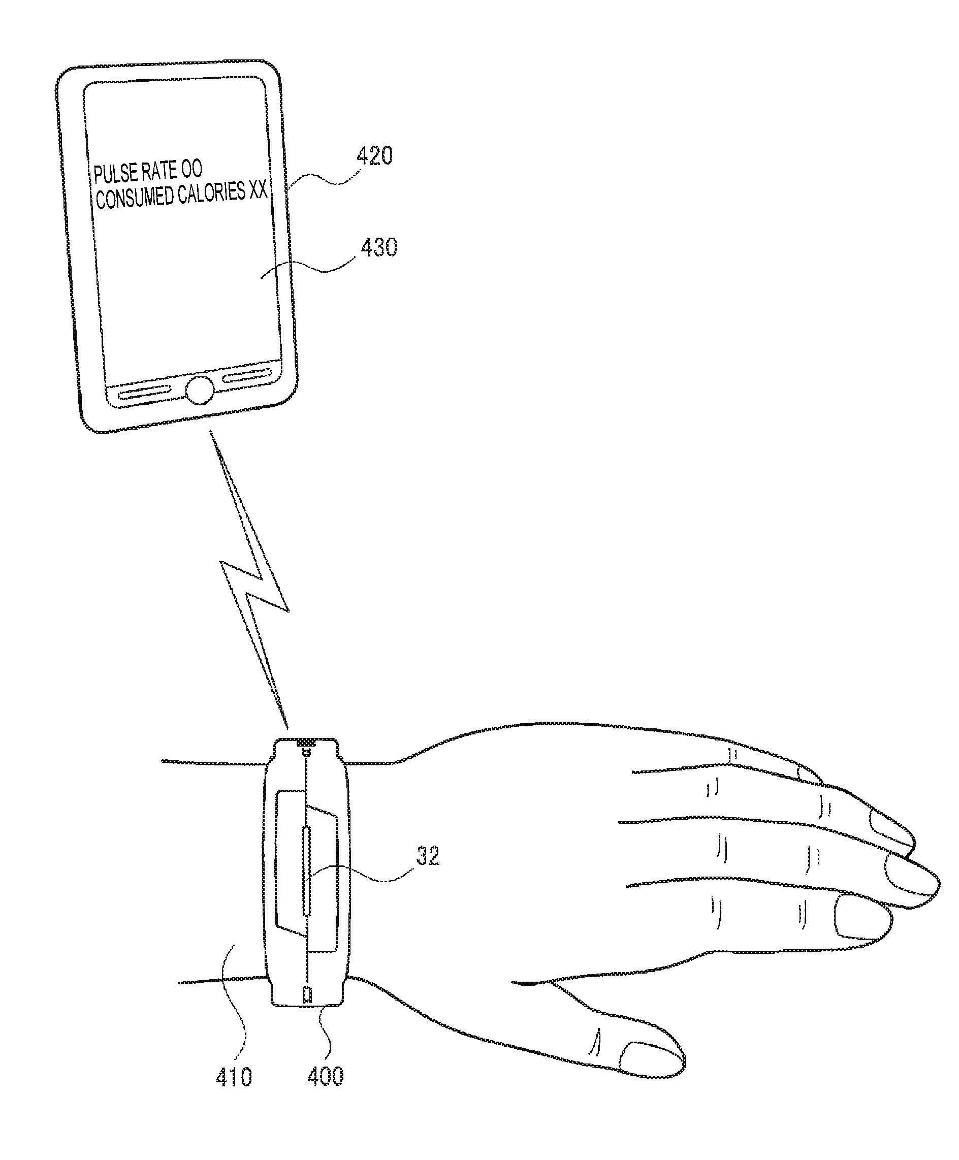
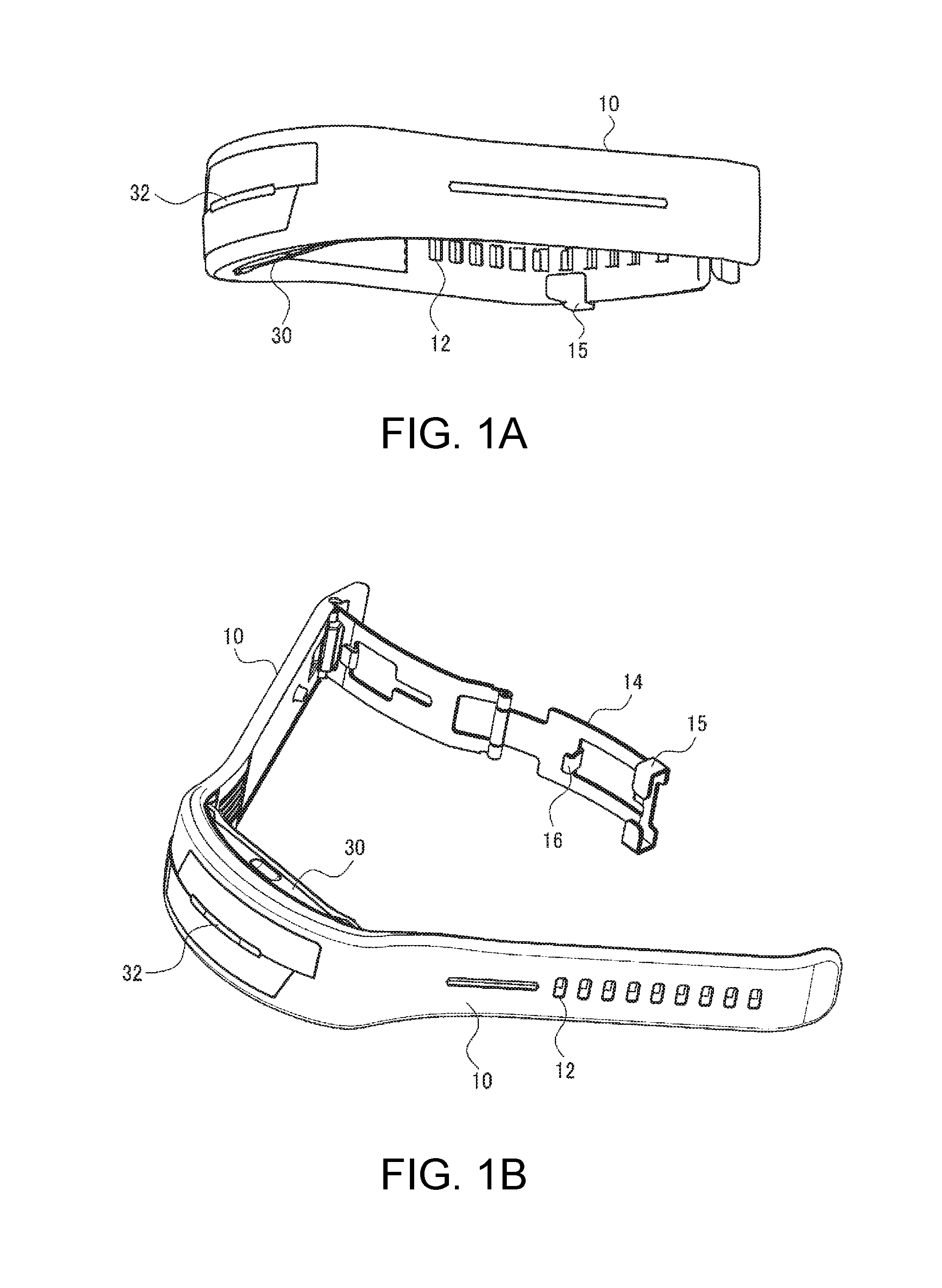
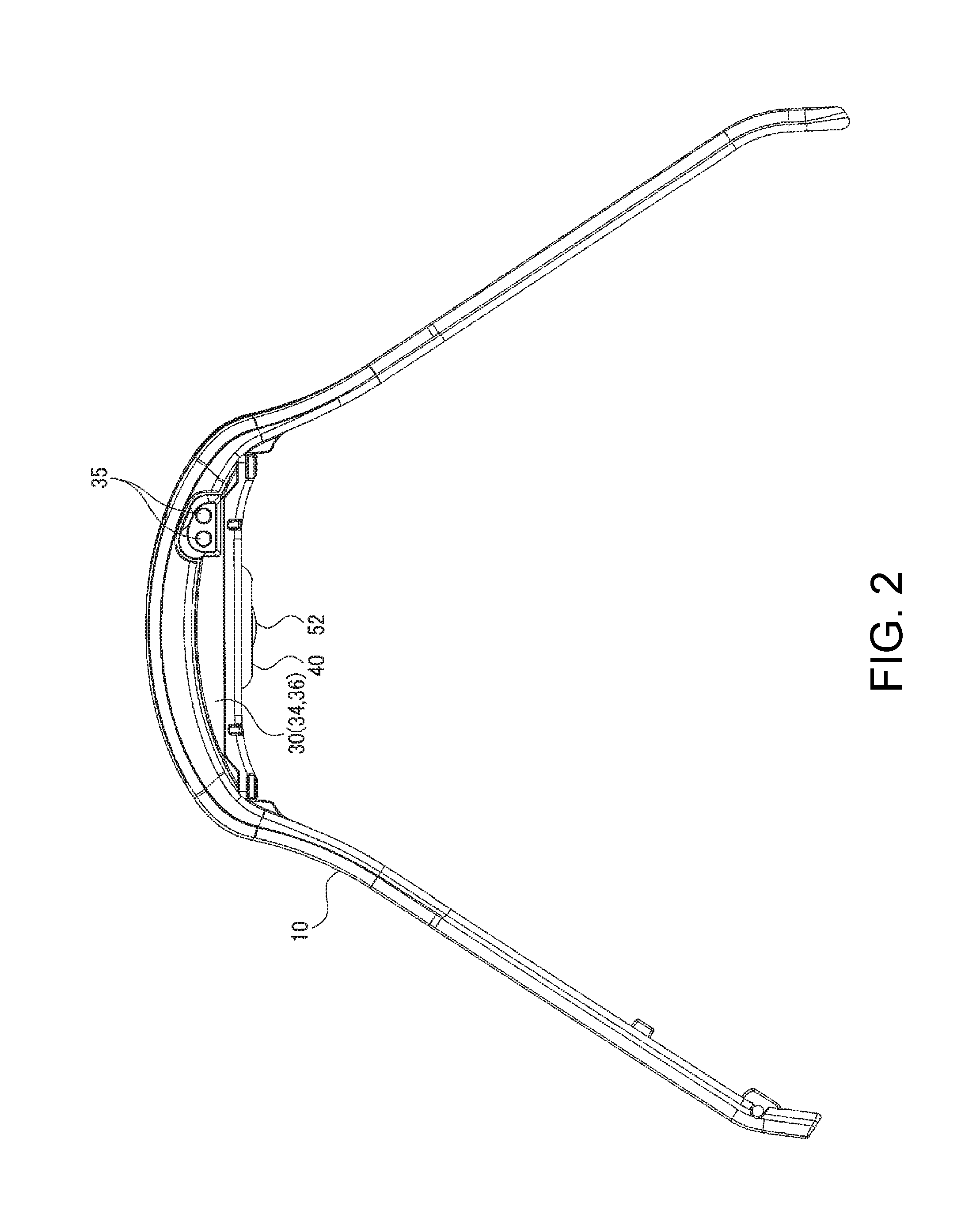
[0080]FIGS. 1A and 1B and FIG. 2 are schematic diagrams illustrating the exterior of a biological information measuring apparatus (biological information detecting apparatus) according to a first embodiment. FIG. 1A is a diagram when the biological information measuring apparatus is seen from the front, FIG. 1B is a diagram when the biological information measuring apparatus of FIG. 1A is obliquely seen from above, and FIG. 2 is a diagram when the biological information measuring apparatus is seen from the side.

[0081]As illustrated in FIGS. 1A and 1B and FIG. 2, the biological information measuring apparatus of this embodiment includes a band portion 10, a case portion 30, and a sensor unit 40 as a biological information measuring module. The case portion 30 is attached to the band portion 10. The sensor unit 40 is provided in the case portion 30. In addition, the biological information mea...

Example

Modification Example 1

[0164]Modification Example 1 of the arrangement of a light emitting unit and a light receiving unit will be described with reference to FIG. 8. In the first embodiment described above, one light emitting unit 150 and one light receiving unit 140 are mounted on the substrate 160 (sensor substrate) so as to be lined up. In a configuration of Modification Example 1, after a first light receiving unit 340 and a second light receiving unit 370 as light receiving units share a light emitting unit 350, the light emitting unit 350, the second light receiving unit 370, and the first light receiving unit 340 are mounted on a substrate 306 in this order so as to be lined up in a row along a predetermined direction.

[0165]In the case of Modification Example 1, the total dimension of a length dimension of a first side 350a constituting the outer circumference of the light emitting unit 350, a length dimension of a second side 350b, a length dimension of a third side 350c, an...

Example

Modification Example 2

[0167]Modification example 2 of the arrangement of a light emitting unit and a light receiving unit will be described with reference to FIG. 9. In a configuration of Modification Example 2, after a first light receiving unit 440 and a second light receiving unit 470 as light receiving units share a light emitting unit 450, the first light receiving unit 440 and the second light receiving unit 470 are mounted on both sides of the light emitting unit 450 so as to be lined up in a row along a predetermined direction.

[0168]In the case of Modification Example 2, the total dimension of a length dimension of a first side 450a constituting the outer circumference of the light emitting unit 450, a length dimension of a second side 450b, a length dimension of a third side 450c, and a length dimension of a fourth side 450d is equivalent to a circumference length of the light emitting unit 450 on the outer circumference. In addition, the total dimension of a length dimensi...


PUM


Abstract

A biological information measuring apparatus includes a sensor unit as a biological information measuring module including a light emitting unit that emits light to an object, and a light receiving unit that receives light from the object. A circumference length of the light emitting unit on the outer circumference is equal to or greater than 1.9 mm and equal to or less than 9.5 mm.

Description

CROSS-REFERENCES TO RELATED APPLICATIONS[0001]This application claims priority to Japanese Patent Application No. 2015-000107, filed Jan. 5, 2015, the entirety of which is hereby incorporated by reference.BACKGROUND[0002]1. Technical Field[0003]The present invention relates to a biological information measuring module, and a biological information measuring apparatus mounted with the biological information measuring module.[0004]2. Related Art[0005]Hitherto, there have been known measuring apparatuses that are worn around body parts, such as a wrist, by a band or the like and measure biological information such as a wearer's pulse waves, and wristwatch type electronic apparatuses having a function of measuring the biological information. For example, JP-A-2000-254105 discloses an arm mounted measuring apparatus which is worn around the arm (wrist) of a wearer (test subject) and is mounted with a biological information measuring module that measures biological information, such as pu...

Claims


Application Information

Patent Timeline
IPC IPC(8): A61B5/024A61B5/02A61B5/04A61B5/022A61B5/00
CPCA61B5/02427A61B5/022A61B5/6824A61B5/04A61B5/02A61B5/0022A61B5/02055A61B5/02438A61B5/4815A61B5/681A61B5/7275A61B2560/0462A61B2562/0233G16H40/63A61B5/24
Inventor INAGAKI, AKIRA
Owner SEIKO EPSON CORP
Why Eureka
Try Eureka