Camera Case With Suspension System

a camera case and suspension technology, applied in the field of storage cases, can solve the problems of numerous drawbacks of various prior art camera cases, and achieve the effects of preventing moisture infiltration, being durable and resistant to the elements, and being convenient to carry

Inactive Publication Date: 2006-12-21
CASE LOGIC
View PDF13 Cites 11 Cited by
  • Summary
  • Abstract
  • Description
  • Claims
  • Application Information

AI Technical Summary

Benefits of technology

[0011] It is still yet another aspect of the present invention to provide a camera storage case that includes handles and locations for the interconnection of a shoulder strap. More specifically, it is desirable to ensure that the storage case is easy to carry and comfortable to the user, thus a plurality of handles and a shoulder strap may be provided thereby giving the user various options for handling and transporting the case.
[0012] It is yet another aspect of the present invention to provide a storage case that is durable and resistant to the elements. More specifically, one embodiment of the present invention is constructed from resilient materials, such as nylon, plastic, rubber, koskin, etc. that are resistant to impacts and fluids. In one embodiment the lower portion of the case is comprised of a water resistant plastic or rigid foam to prevent the infiltration of moisture and provide structural support. Also, embodiments of the present invention include zippers that seal closable compartments that include water resistant sheaths that substantially prevent liquid from entering the storage compartments of the camera storage case when the compartments are sealed.

Problems solved by technology

Unfortunately, there are numerous drawbacks of various prior art camera cases.
One drawback of prior art camera cases is that they are generally fashioned for a single camera model.
However, this static configuration methodology ignores the fact that camera enthusiasts often have a plurality of cameras of various shapes and sizes wherein many cases are required to protect all of their equipment.

Method used


Image

  • Camera Case With Suspension System
  • Camera Case With Suspension System
  • Camera Case With Suspension System

Examples


Embodiment Construction

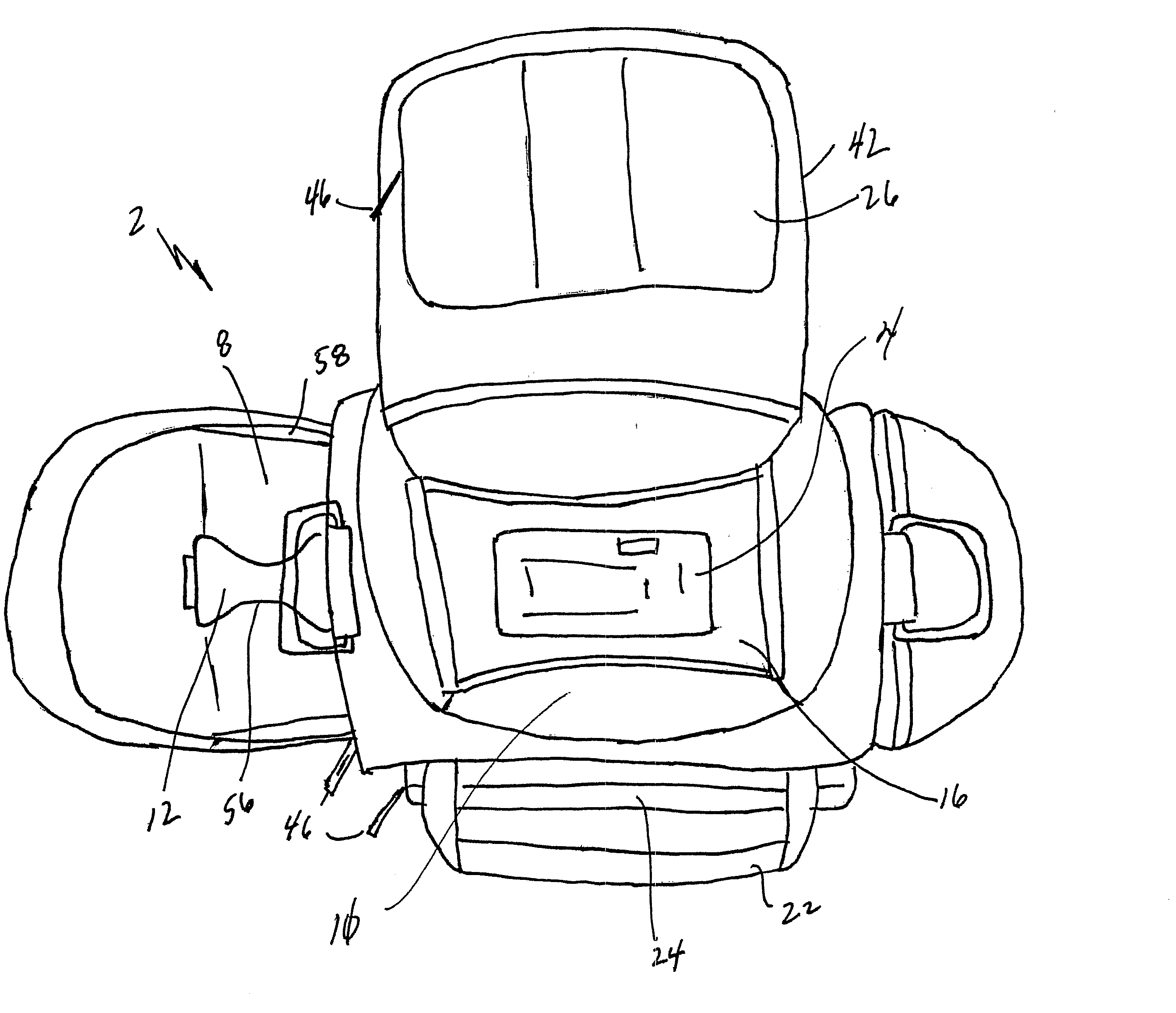
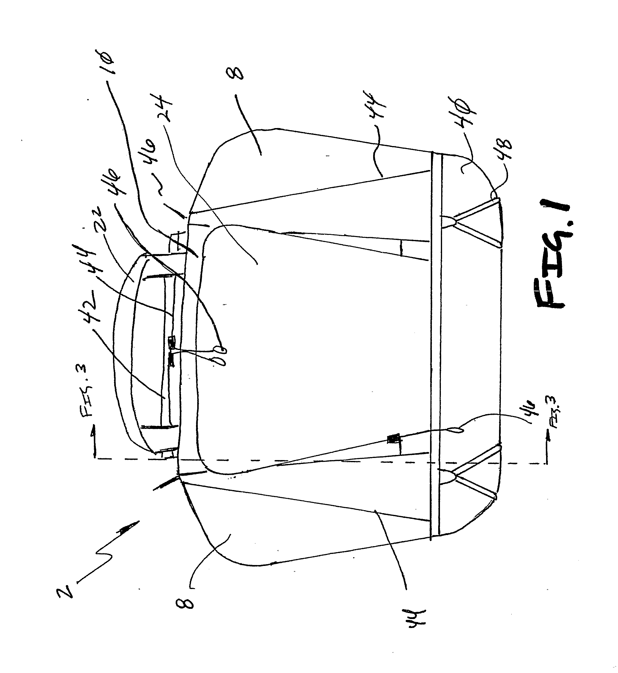
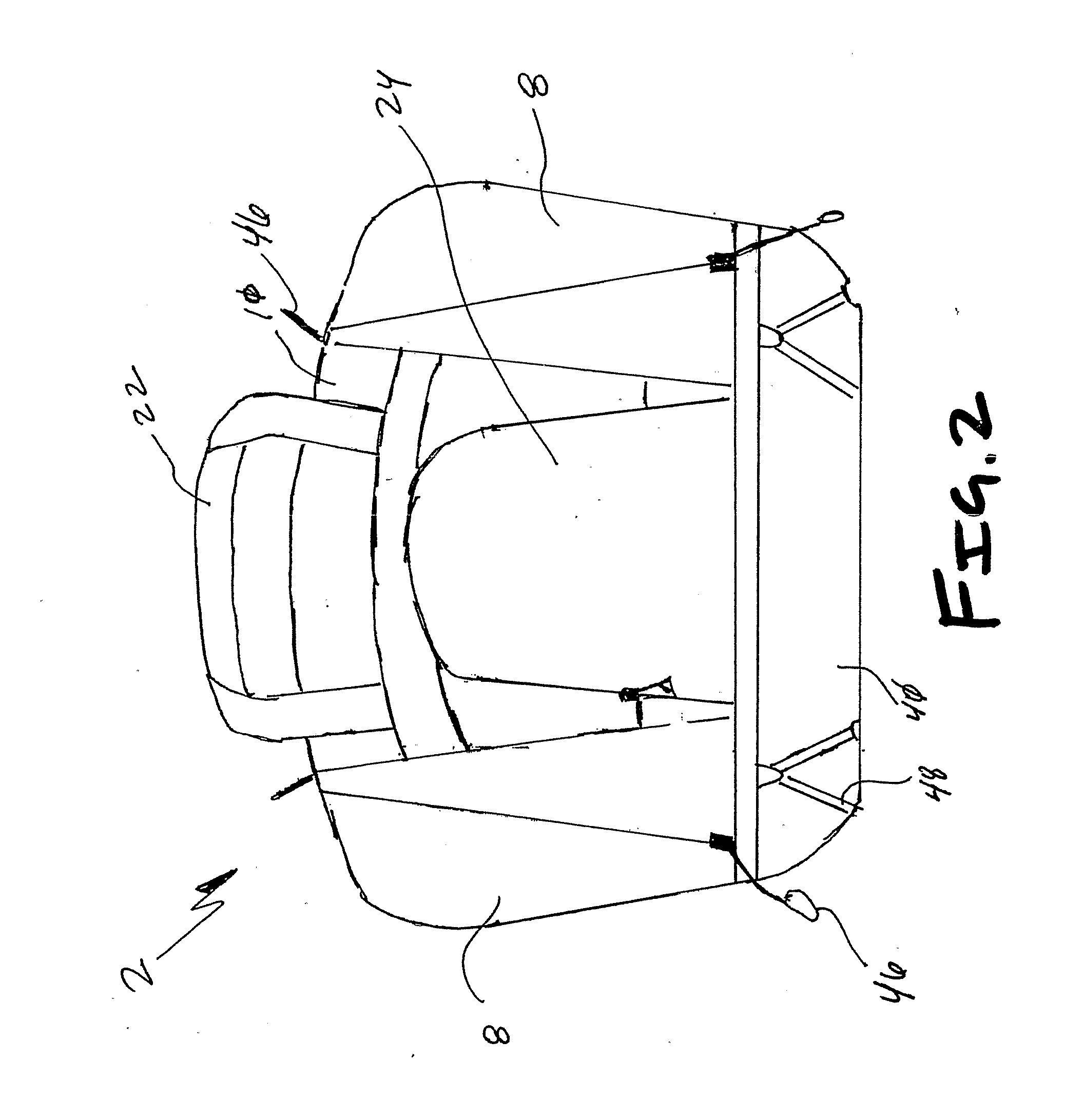
[0031] Referring now to FIGS. 1-8, a storage case 2 of one embodiment of the present invention is shown. More specifically, the storage case 2 is shown that includes a plurality of compartments that provide storage locations for cameras 4, lenses 6, film, instructions, maps, and supplies, and other items generally associated with photography as well as other electronic devices. Preferably, the camera storage case 2 includes lens compartments 8 that are selectively openable and hingedly interconnected to the main storage compartment of the case 10. The lens storage compartments 8 also may include an adjustable divider 12, which is selectively interconnected to the sidewalls of the lens compartment 8, and which is padded for added protection of the lenses. Thus, a user may selectively position the divider 12 to accommodate various sizes of lenses or alternatively simply remove the divider 12 to provide a storage area for larger items or an auxiliary storage case 14.

[0032] Further emb...


PUM


Abstract

A storage case for an electronics device is provided that includes a main storage compartment with a selectively adjustable suspension system that selectively interconnects to sidewalls of the main storage compartment, thus providing the user with the ability to customize the storage area within the main storage compartment. The suspension system also is resiliently deflectable to help dissipate shock loads resulting from drops, for example. The storage case in one embodiment is designed for cameras and may also include a plurality of lens storage compartments with selectively adjustable lens dividers, storage pockets, and storage compartments.

Description

[0001] This application claims the benefit of U.S. Provisional Patent Application Ser. No. 60 / 687,294, filed Jun. 3, 2005, which is incorporated by reference in its entirety herein.FIELD OF THE INVENTION [0002] The present invention relates generally to storage cases for electronic devices and other impact sensitive devices. More specifically, one embodiment of the present invention is a camera storage case with a selectively adjustable suspension system that provides an inner storage volume that may be customized, while also providing adequate protection to the electronic device stored therein. BACKGROUND OF THE INVENTION [0003] Expensive electronic equipment, such as cameras, require a high level of protection. Often storage cases are employed to provide the required protection from the elements and from impacts, which may be encountered by stored cameras. Unfortunately, there are numerous drawbacks of various prior art camera cases. [0004] One drawback of prior art camera cases i...

Claims


Application Information

Patent Timeline
Patent Type & Authority Applications(United States)
IPC IPC(8): B65D85/38B65D85/46
CPCA45C11/38A45C2013/025A45C13/02
Inventor HASSETT, ERIC S.
Owner CASE LOGIC
Why Eureka
Try Eureka