
Receiver for orthogonal frequency division multiplexing transmission

a frequency division multiplexing and receiver technology, applied in the field of receivers for orthogonal frequency division multiplexing transmission, can solve the problems of inability to average or linearly interpolate two channel estimation values, and achieve the effects of fast data demodulation, reduced processing delay, and suppressing residual noise components

Inactive Publication Date: 2006-12-21
FUJITSU LTD
View PDF9 Cites 59 Cited by
  • Summary
  • Abstract
  • Description
  • Claims
  • Application Information

AI Technical Summary

Benefits of technology

[0046] As a result of the abovementioned characterizing construction of the present invention, the following effects are obtained.
[0047] First of all, since differences in the amount of phase rotation caused by deviation in the FFT extract position are corrected, the channel estimation values for several frames can be averaged and used; accordingly, the residual noise component can be suppressed (and the like), so that high-precision channel estimation is possible.
[0048] Secondly, since differences in the amount of phase rotation caused by deviation in the FFT extract position are corrected, the channel estimation value for an immediately preceding frame can be used for the demodulation of the next frame; accordingly, processing delay can be reduced so that fast data demodulation is possible.
[0049] Third, since differences in the amount of phase rotation caused by deviation in the FFT extract position are corrected, high-precision Doppler frequency estimation, carrier frequency offset estimation and SIR estimation are possible.

Problems solved by technology

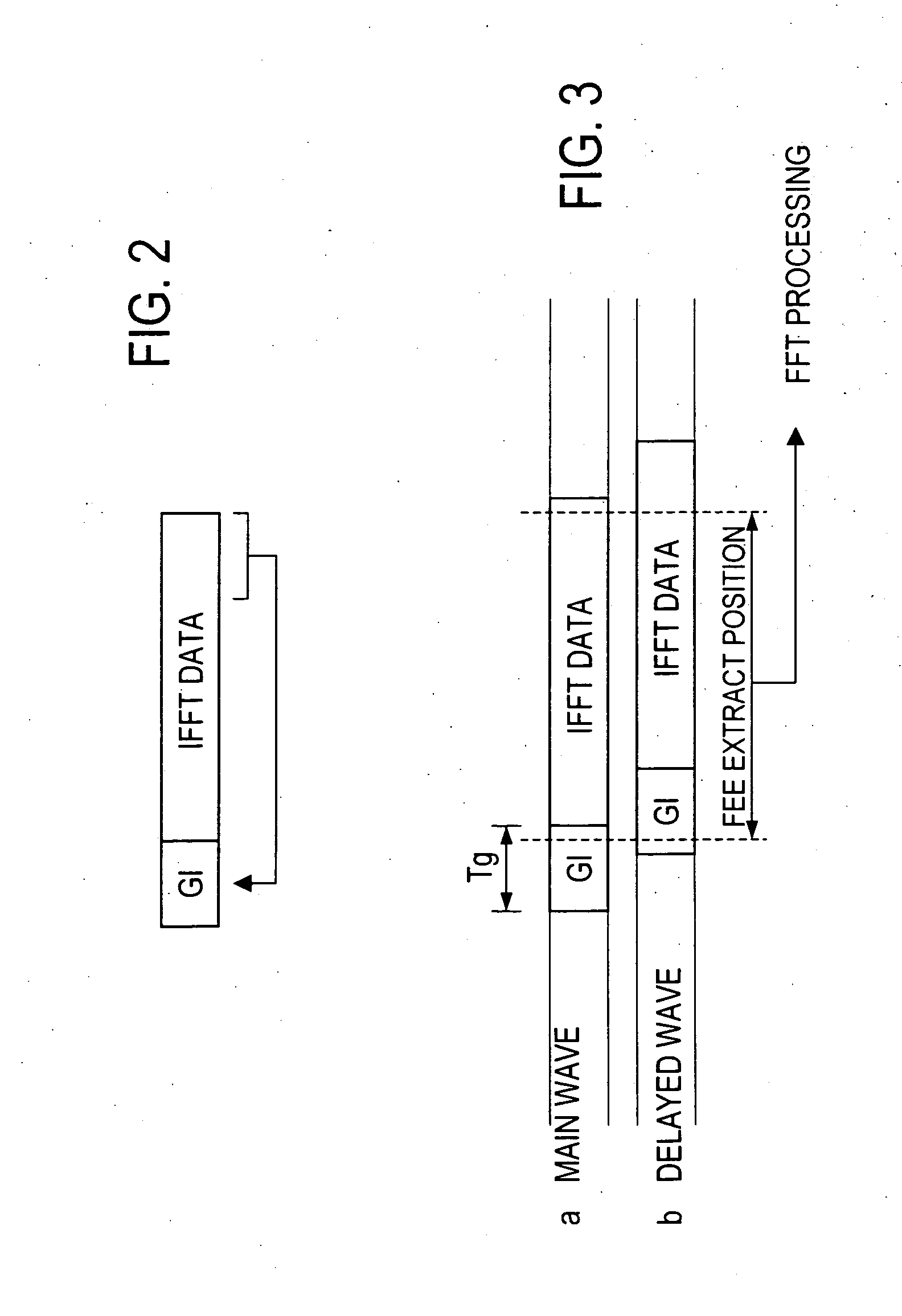
However, in cases where an alteration of the FFT extract position is made between the frame n and frame n+1, the following problem may arise: namely, the averaging or linear interpolation of two channel estimation values may be impossible.

Method used


Image

  • Receiver for orthogonal frequency division multiplexing transmission
  • Receiver for orthogonal frequency division multiplexing transmission
  • Receiver for orthogonal frequency division multiplexing transmission

Examples


embodiments

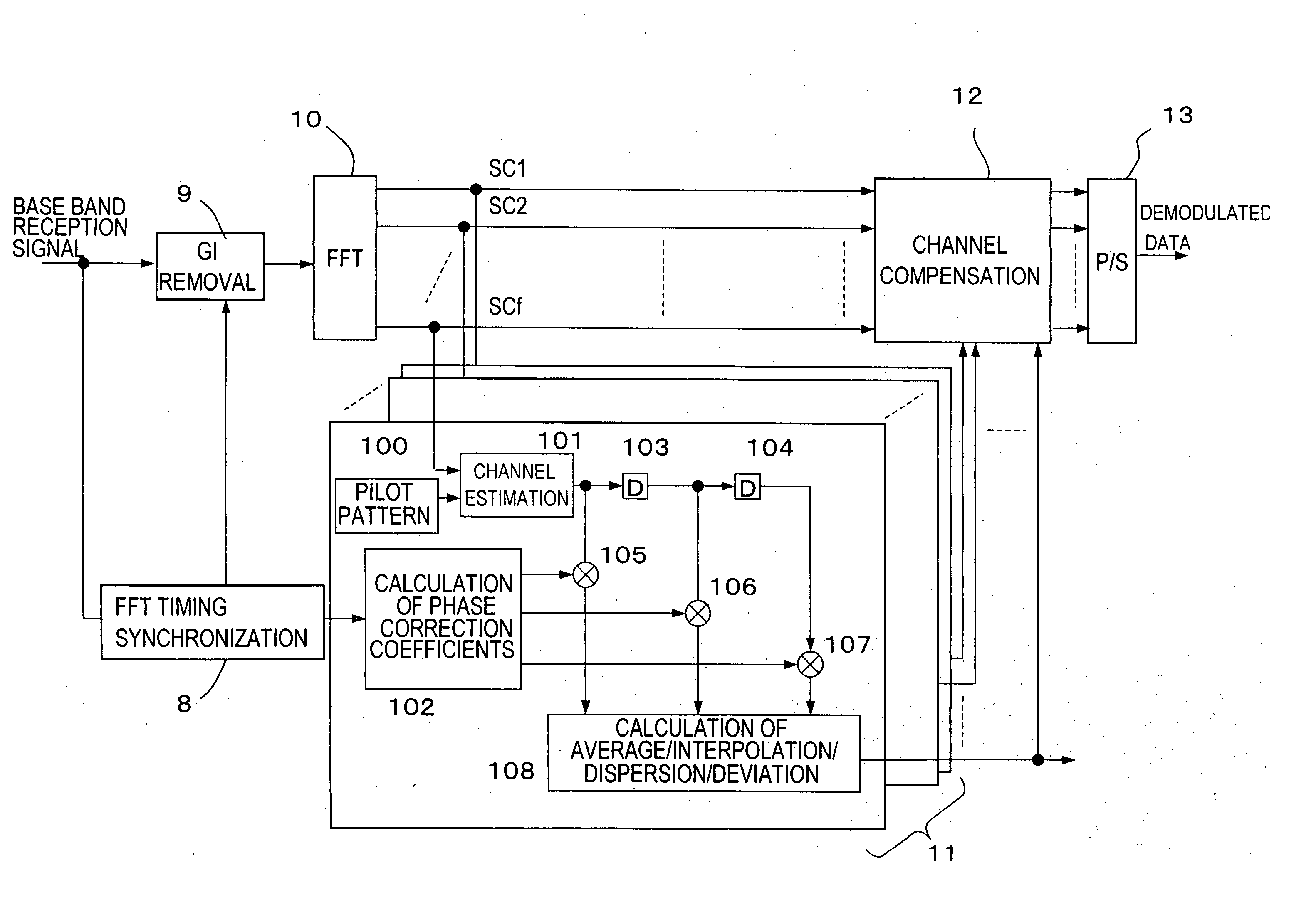
[0067]FIG. 5 shows the construction of an embodiment of the receiver in the OFDM transmission system according to the present invention. In FIG. 5, the receiver circuit (Rx) 7 is omitted, and only the portions constructed according to the characterizing features of the present invention are shown. Furthermore, the same reference numbers are assigned to parts that are the same as in FIG. 1. The same is true in other embodiments described later.

[0068] In FIG. 5, as a characterizing feature, the channel estimating part 11 has, for each subcarrier, a subcarrier handling part in which an existing pilot pattern storage part 100, a channel estimating circuit 101 that performs channel estimation based on the pilots, a phase correction coefficient calculating circuit 102 corresponding to the FFT timing, delay circuits 103 and 104, phase correction multiplying circuits 105 through 107, and a calculating circuit 108 that performs averaging, interpolation, dispersion or deviation calculations ...


PUM


Abstract

Channel estimation values of pilot symbols for channel compensation of data symbols in an OFDM receiver can be used, even in cases where FFT extract position differs for each frame. The OFDM receiver is characterized in having a circuit which calculates the amount of phase rotation that is generated by the difference in timing at which the individual symbols are extract as objects of a fast Fourier transform when the fast Fourier transform processing is performed by a fast Fourier transform circuit, and further a circuit which corrects the amount of phase rotation for the channel estimation value determined by a channel estimating circuit.

Description

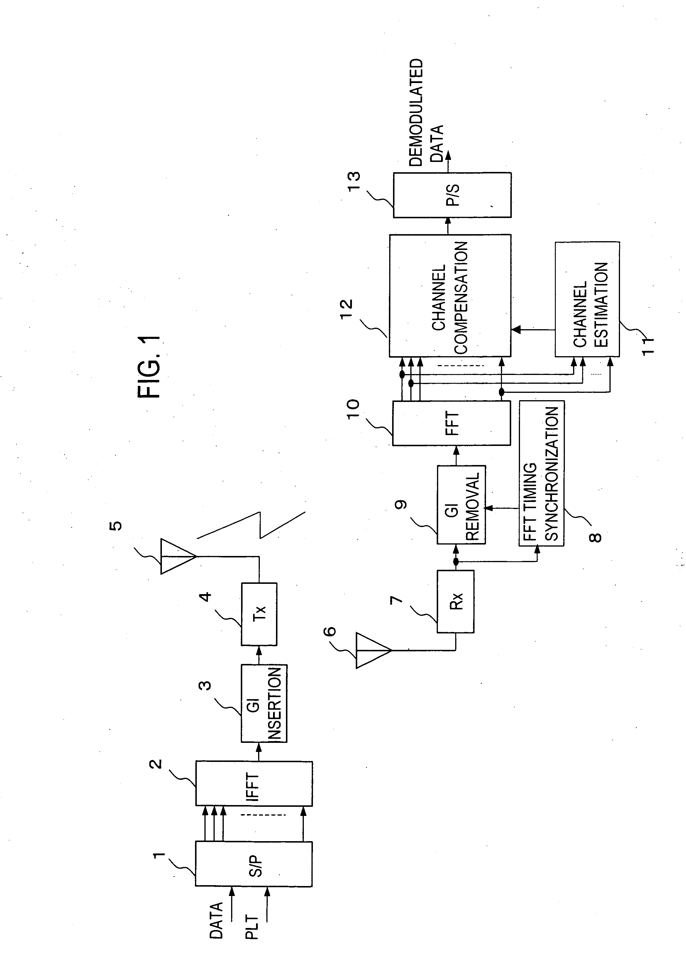
CROSS-REFERENCE TO RELATED APPLICATIONS [0001] This application is based upon and claims the benefit of priority from the prior Japanese Patent Application No. 2005-179093, filed on Jun. 20, 2005, the entire contents of which are incorporated herein by reference. BACKGROUND OF THE INVENTION [0002] 1. Field of the Invention [0003] The present invention relates to a receiver for orthogonal frequency division multiplexing transmission, and more particularly to a receiver for orthogonal frequency division multiplexing transmission which allows high-precision channel estimation. [0004] 2. Description of the Related Art [0005] Orthogonal frequency division multiplexing (OFDM) transmission systems which make it possible to maximize the frequency utilization efficiency are used in wireless communications systems that aim at high-speed data communications. [0006] In the case of orthogonal frequency division multiplexing (hereafter referred to simply as “OFDM”) transmission systems, the band ...

Claims


Application Information

Patent Timeline
IPC IPC(8): H04K1/10
CPCH04L25/022H04L27/2695H04L27/2665H04L25/0232H04L27/2675
Inventor SEKI, HIROYUKIJITSUKAWA, DAISUKESHIIZAKI, KOTAROKAKURA, YOSHIKAZUTAKAMICHI, TORUKOYANAGI, KENJIKAWAI, HIROYUKI
Owner FUJITSU LTD
Learn More