Method for encoding moving image and method for decoding moving image

a technology for moving images and encoding methods, applied in the field of moving image encoding, can solve the problems of not being able to transmit not being able to handle such an enormous amount of information as it is in digital form, and being unable to transmit images on televisions and images taken by cameras directly through isdn,

Active Publication Date: 2006-12-21
PANASONIC CORP
View PDF15 Cites 66 Cited by
  • Summary
  • Abstract
  • Description
  • Claims
  • Application Information

AI Technical Summary

Benefits of technology

[0049] In order to achieve the aforementioned object, a moving image encoding method according to the present invention is a moving image encoding method for encoding an inputted picture on a block-by-block basis after dividing the picture into blocks, the picture including luminance components and chrominance components, the method including: a prediction encoding step of encoding the picture by referring to an encoded area in the picture or a different encoded picture; a reconstructed picture generation step of reconstructing the picture using encoded data generated in the prediction encoding step; and a deblocking step of reducing distortion by filtering a boundary between blocks of the reconstructed picture generated in the reconstructed picture generation step, wherein in the deblocking step, filters are respectively applied to the luminance components and the chrominance components: a type of the filters is selected based on encoding information of each luminance component and the selected filter is applied to the luminance component; and a filter selected for a luminance component, which belongs to a same field as a chrominance component and corresponds to the chrominance component, is applied to the chrominance component.
[0050] Accordingly, the same type of deblocking filter is applied to the luminance components and chrominance components in the same field. Therefore, an encoding so as to generate a consistent image when the image is displayed in the interlaced-scan form after the image is decoded. Further, it is possible to combine a structure of the present invention easily into the conventional structure because there are very few changes from the conventional structure.
[0051] Also, a moving image decoding method according to the present invention is a moving image decoding method for decoding encoded moving image data obtained by encoding, on a block-by-block basis, a picture which is divided into blocks, the picture including luminance components and chrominance components, the method including: a prediction decoding step of decoding the picture by referring to a decoded area in the picture or a different decoded picture; and a deblocking step of reducing distortion by filtering a boundary between blocks of the decoded picture generated in said prediction decoding step, wherein in the deblocking step, filters are respectively applied to the luminance components and the chrominance components: a type of the filters is selected based on encoding information of the luminance component and the selected filter is applied to each luminance component; and a filter selected for a luminance component, which belongs to a same field as a chrominance component and corresponds to the chrominance component, is applied to the chrominance component.
[0052] Accordingly, a same type of deblocking filter is applied to the luminance components and chrominance components in the same field. Further, it is possible to combine a structure of the present invention easily into the conventional structure because there are very few changes from the conventional structure.
[0054] According to the moving image encoding method by the present invention, same type of deblocking filter is applied to the luminance components and the chrominance components in the same field. Therefore, it is possible to perform encoding so as to generate a consistent image when the image is displayed in the interlaced-scan form after the image is decoded. Further, it is possible to combine a structure of the present invention easily into the conventional structure because there are few changes from the conventional structure.
[0055] In addition, according to the moving image decoding method by the present invention, a same type of deblocking filter is applied to the luminance components and chrominance components in the same field. Therefore, it is possible to generate a consistent image in the case of displaying the image in the interlaced-scan form. Further, it is possible to combine a structure of the present invention easily into the conventional structure because there are very few changes from the conventional structure.

Problems solved by technology

However, if the amount of information carried by each of the mentioned information media is estimated as the amount of digital information, while the amount of information for 1 character in the case of text is 1 to 2 bytes, the amount of information required for sound is 64 Kbits per second (telephone quality), and 100 Mbits or over per second becomes necessary for moving images (current television receiving quality), it is not realistic for the information media to handle such an enormous amount of information as it is in digital form.
For example, although video phones are already in the actual use via Integrated Services Digital Network (ISDN) which offers a transmission speed of 64 kbps to 1.5 Mbps, it is impossible to transmit images on televisions and images taken by cameras directly through ISDN.
Therefore, it is more likely that the color components are decimated for use.
Consequently, the picture quality is degraded in the chrominance components in the bottom field so that the image is not consistent when it is displayed in the interlaced-scan form.
As described in the above, in the case where the image to be displayed in the interlaced-scan form is encoded and decoded in the frame structure, there is a problem that an inappropriate type of filter is applied because there is a case where the type of filter applied to the chrominance components is determined by referring to the luminance components in a different field.

Method used


Image

  • Method for encoding moving image and method for decoding moving image
  • Method for encoding moving image and method for decoding moving image
  • Method for encoding moving image and method for decoding moving image

Examples


first embodiment

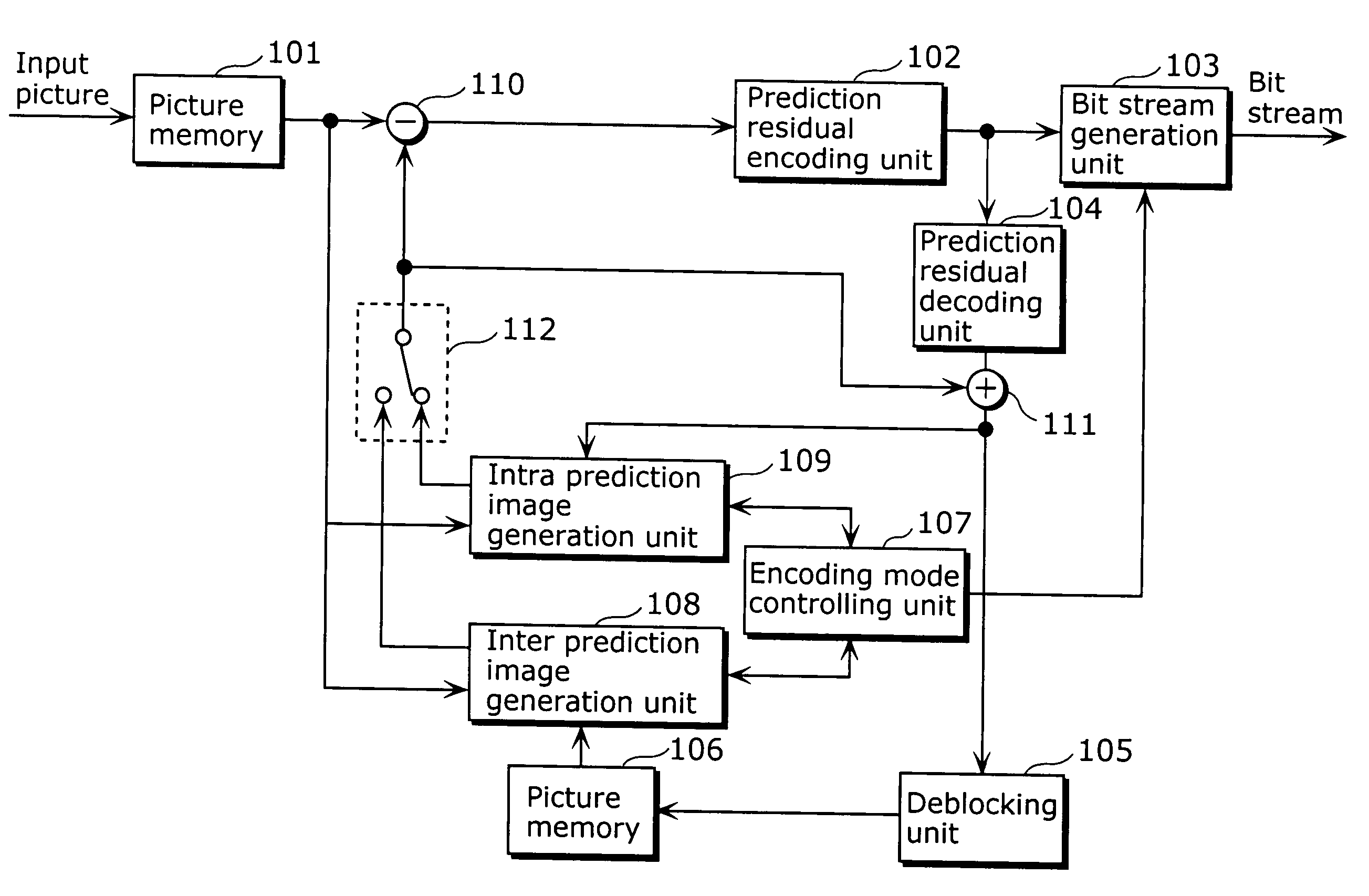
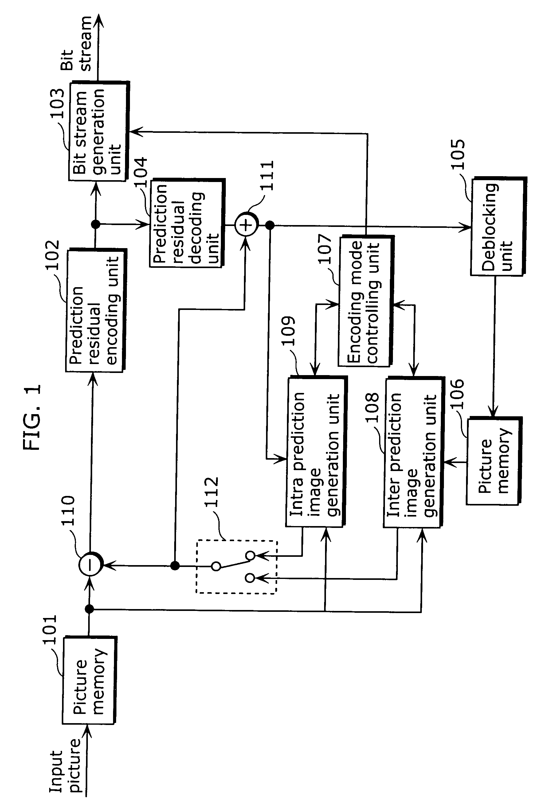
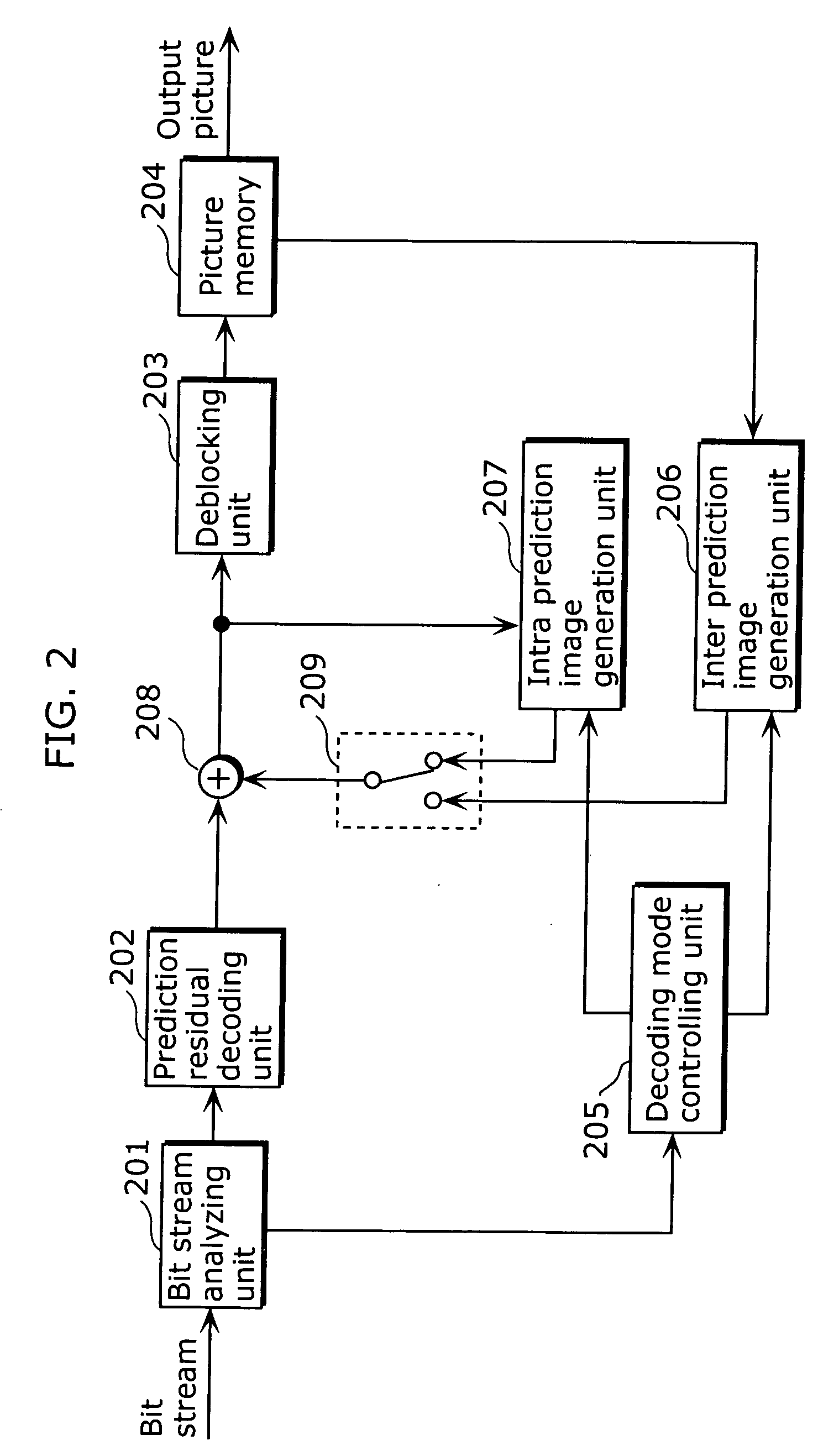
[0074] The structure of a moving image encoding apparatus according to a flow of encoding processing as a whole in a first embodiment of the present invention is completely same as the conventional structure explained using FIG. 1. Therefore, an explanation about the same structure is omitted in here. The structure of the moving image encoding apparatus only differs from the conventional structure in a deblocking method used by the deblocking unit 105 shown in FIG. 1. Also, the structure of the moving image decoding apparatus according to a flow of decoding processing as a whole is completely same as the conventional structure explained using FIG. 2. Therefore, the explanation is omitted in here. It differs from the conventional structure only in a deblocking method used by a deblocking unit 203 shown in FIG. 2.

[0075] Hereafter, it is explained in detail about the processing in the deblocking units 105 and 203. Here, the processing details in the encoding processing and in the deco...

second embodiment

[0106] In addition, by recording a program for realizing the layout of the moving image encoding method or the moving image decoding method as shown in each of the above-mentioned embodiments, on a recording medium such as a flexible disk, it becomes possible to perform the processing as shown in the above embodiment easily in an independent computer system.

[0107]FIG. 13 are diagrams of a recording medium for recording a program for realizing the moving image encoding method and the moving image decoding method in the above embodiment in the computer system.

[0108]FIG. 13B shows the front view of a flexible disk and the schematic cross-section, as well as a flexible disk itself, whereas FIG. 13A shows an example of a physical format of the flexible disk as a recording medium body. A flexible disk FD is contained in a case F, a plurality of tracks Tr are formed concentrically on the surface of the disk in the radius direction from the periphery, and each track is divided into 16 sec...


PUM


Abstract

In the case where a deblocking filter applied to a luminance component is referred to and applied to a chrominance component, by converting a pixel position of the chrominance component so as to have a pixel position of a luminance component which belongs to a same field as the chrominance component (F7a) and referring to the luminance component, the present invention makes it possible to generate a more natural image by filtering the luminance component and the chrominance component with same strength when the image is displayed in an interlaced-scan form.

Description

TECHNICAL FIELD [0001] This invention relates to a moving image encoding method for encoding a moving image signal after dividing the moving image signal composed of luminance components and chrominance components into blocks, and to a moving image decoding method for decoding the encoded data. BACKGROUND ART [0002] In the age of multimedia which integrally handles audio, video and other pixel values, existing information media, specifically, newspaper, magazine, television, radio, telephone and the like through which information is conveyed to people, have recently come to be included in the scope of multimedia. Generally, multimedia refers to something that is represented by associating not only characters, but also graphics, sound, and especially images and the like, together, but in order to include the aforementioned existing information media in the scope of multimedia, it becomes a prerequisite to represent such information in a digital form. [0003] However, if the amount of ...

Claims


Application Information

Patent Timeline
Patent Type & Authority Applications(United States)
IPC IPC(8): G06K9/36G06K9/40H04N7/26H04N11/04
CPCH04N11/042H04N19/172H04N19/527H04N19/117H04N19/186H04N19/61H04N19/80H04N19/86
Inventor ABE, KIYOFUMIKADONO, SHINYA
Owner PANASONIC CORP
Why Eureka
Try Eureka