
Intraluminal device with unsymmetric tapered beams

a technology of unsymmetric tapered beams and intraluminal devices, which is applied in the field of medical devices, can solve the problems of intraluminal devices that exert radial force, intraluminal devices may collapse into low profiles, and the strain in the stent structure is not completely relieved

Active Publication Date: 2006-12-21
COOK MEDICAL TECH LLC +1
View PDF6 Cites 6 Cited by
  • Summary
  • Abstract
  • Description
  • Claims
  • Application Information

AI Technical Summary

Benefits of technology

The patent describes an intraluminal device that includes a first beam, a second beam, and a bend connecting them. The bend is elastic and allows for collapsible and expandable configurations. The first beam has a tapered width on its first and second sides, and the second beam has a tapered width on its third and fourth sides. The device also includes struts in a stent, with an included angle of less than 5 degrees in the low profile. The technical effects of the invention include improved flexibility, reduced strain, and a more uniform distribution of strain.

Problems solved by technology

As a result, the intraluminal device may be collapsed into a low profile by flexing the bends.
This introduces strain into the bends, which typically causes the intraluminal device to exert radial force.
As a result, the strain in the stent structure is not completely relieved after implantation, and the stent structure remains permanently under a lower amount of strain.
One problem with current stent structures is that they may weaken and / or fail due to fatigue in the bends that interconnect the struts.
Fatigue may occur because stents are frequently implanted into organs like arteries that pulse in diameter each time that the heartbeats.
Over many strain cycles, the structure of the stent may eventually become permanently damaged.
One risk is that fatigue damage may cause bends in the stent structure to fracture and break.
This may result in undesirable tissue damage and may reduce the effectiveness of the stent.
Moreover, fatigue behavior, in addition to considerations of the high initial strain introduced into the stent during delivery, may limit the design choices available to makers of stents.
However, stents with longer struts may be subject to undesirable tissue prolapse after implantation, in which tissues of the lumen wall grow around and encapsulate the stent structure.
However, stents with shorter struts may be subject to higher strain levels which may damage the structure of the stent.

Method used


Image

  • Intraluminal device with unsymmetric tapered beams
  • Intraluminal device with unsymmetric tapered beams
  • Intraluminal device with unsymmetric tapered beams

Examples


Embodiment Construction

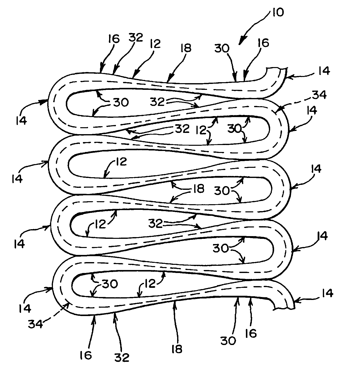
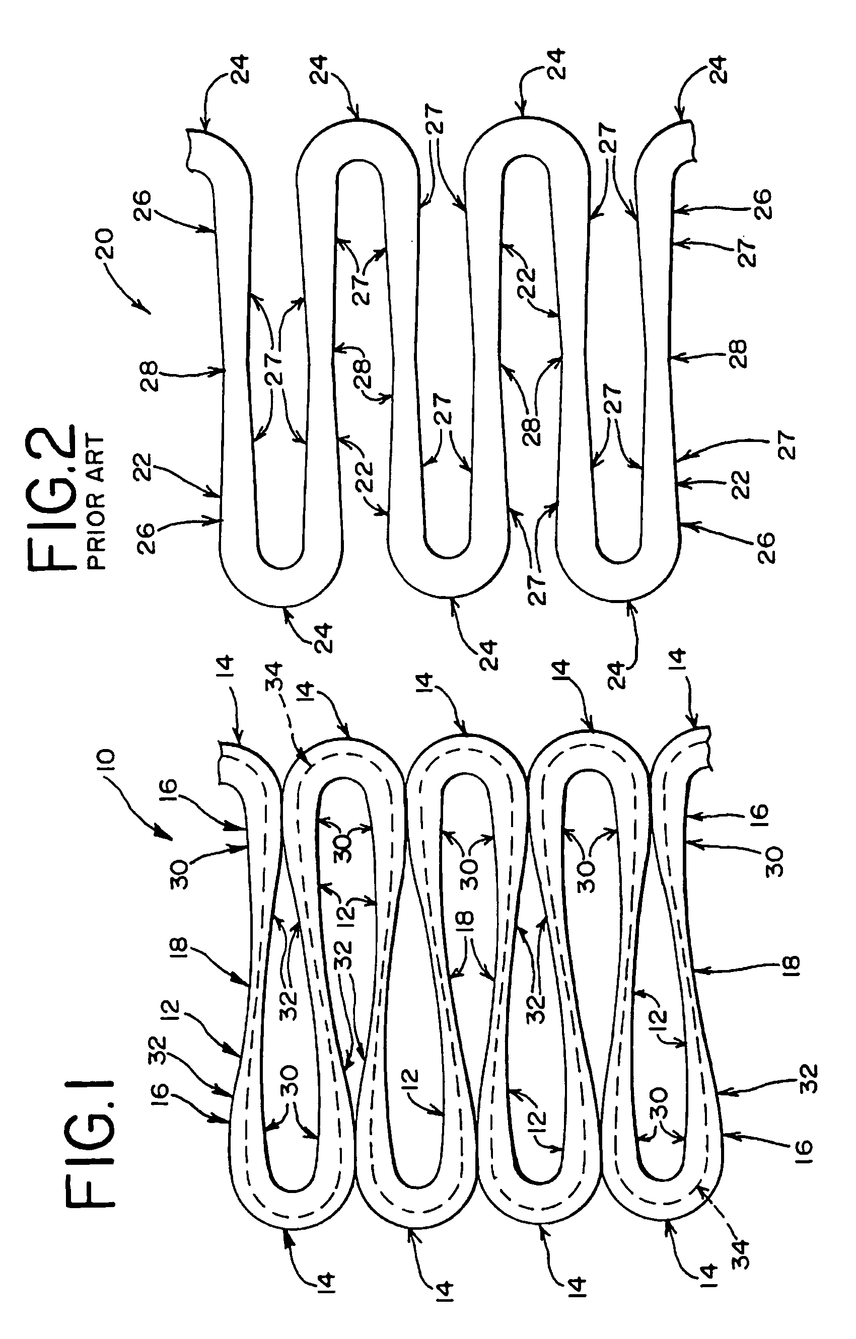
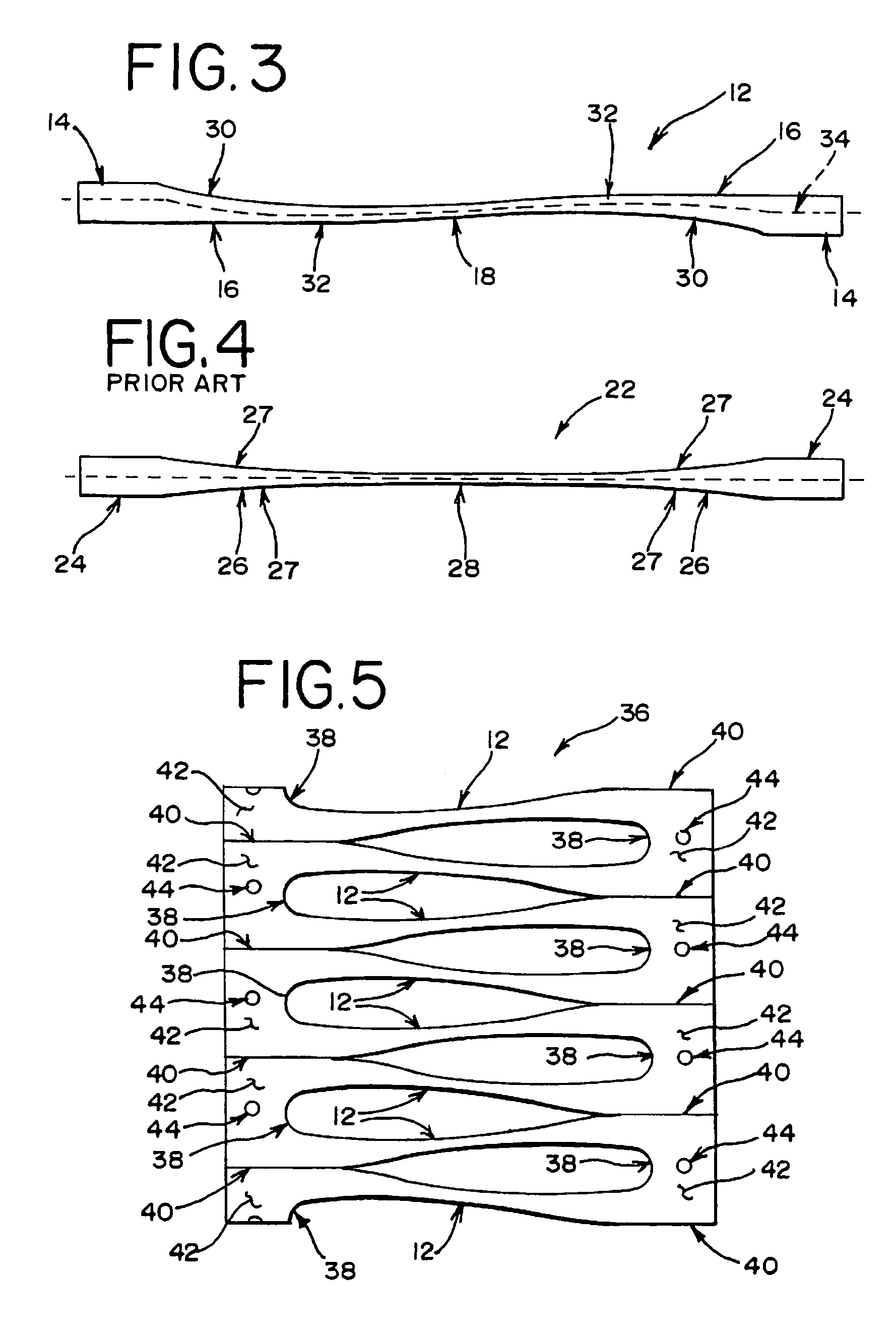
[0054] Referring now to the figures, and particularly to FIG. 1, an improved stent structure 10 is shown. The stent structure 10 includes a series of struts 12, or beams 12, interconnected by a series of bends 14. Preferably, the stent structure 10 is made from an elastic material like nitinol or stainless steel. The stent structure 10 may be made by conventional manufacturing techniques, such as laser cutting the structure from a metal cannula or other known methods. As shown in FIG. 1, each strut 12 is formed from two end portions 16 that are connected together by a middle portion 18. Each end portion 16 of the struts 12 is further connected to a bend 14 which is connected on each side to different struts 12. The bends 14 on opposing ends of each strut 12 face in opposite directions. Thus, the bends 14 interconnect together the series of struts 12 to form a stent structure 10. The bends 14 and struts 12 may also be further connected to other struts and bends or other structures to...


PUM


Abstract

A beam is provided for intraluminal devices. The beam is defined by a first side surface and a second side surface. The first side surface is tapered at a different rate than the second side surface. One advantage of the beam is that strain which is normally concentrated in adjacent, interconnected bends is redirected onto the length of the beam. This may increase the fatigue life of intraluminal devices or may be used to fashion new structures with improved performance.

Description

[0001] This application claims priority to U.S. Provisional Application No. 60 / 690,824, filed Jun. 15, 2005, which is hereby incorporated by reference herein. RELATED APPLICATIONS [0002] This application is related to U.S. patent application Ser. No. ______ (Attorney Docket No. 8627-859), incorporated herein by reference and entitled Intraluminal Device With Improved Tapered Beams, filed by the same inventors on the same day as the present application.BACKGROUND [0003] The present invention relates generally to medical devices and more particularly to intraluminal devices suitable for percutaneous transluminal delivery into a body. [0004] A variety of intraluminal devices are known to those in the medical arts, including stents, stent-grafts, filters, occluders, artificial valves and other endoprosthetic devices. For example, stents have now become a relatively common device for treating a number of organs, such as the vascular system, colon, biliary tract, urinary tract, esophagus,...

Claims


Application Information

Patent Timeline
Patent Type & Authority Applications(United States)
IPC IPC(8): A61F2/06
CPCA61F2250/0036A61F2/915
Inventor ROEDER, BLAYNE A.LEEWOOD, ALAN R.
Owner COOK MEDICAL TECH LLC
Learn More