
Backlighting apparatus and method

Inactive Publication Date: 2006-12-28
TIR TECH LP
View PDF5 Cites 43 Cited by
  • Summary
  • Abstract
  • Description
  • Claims
  • Application Information

AI Technical Summary

Benefits of technology

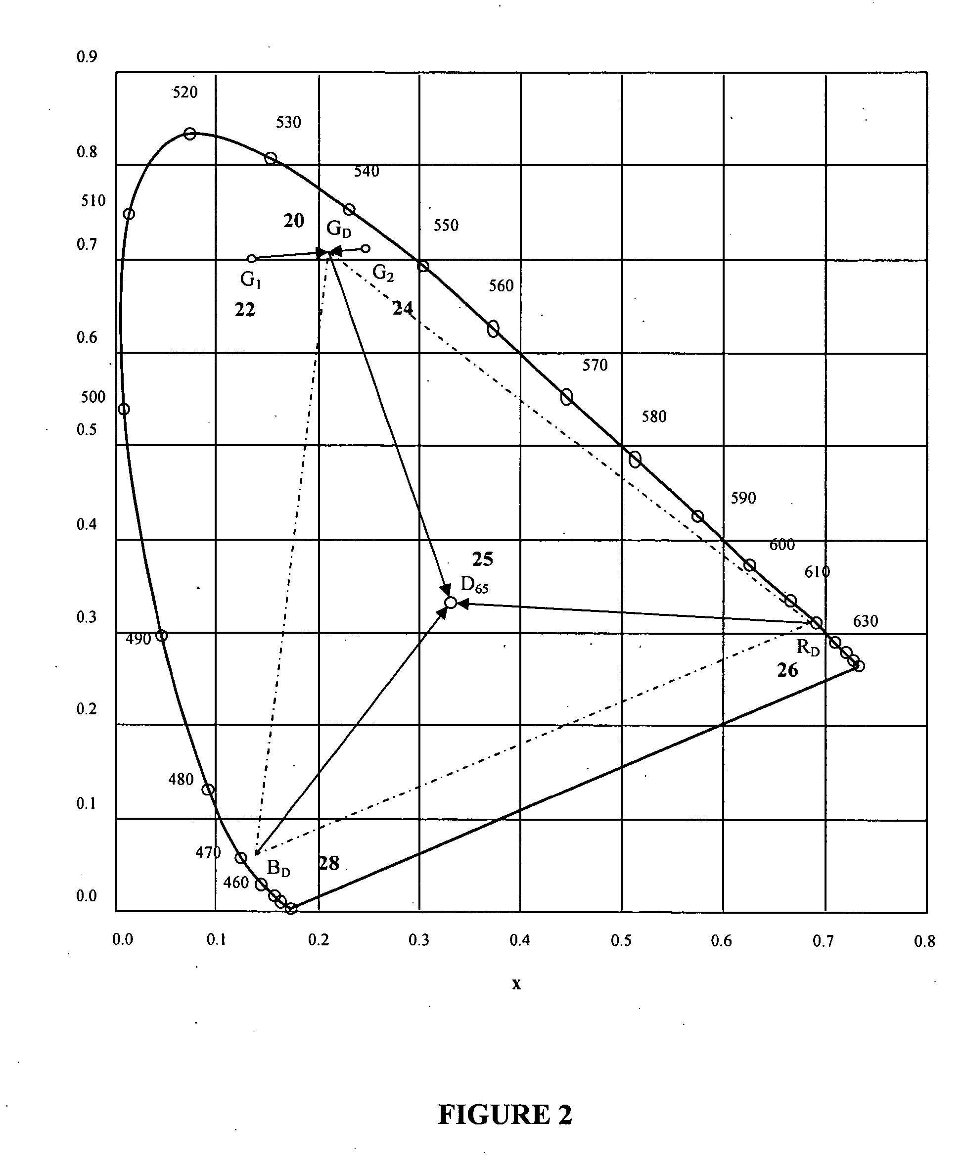
[0018] An object of the present invention is to provide a backlighting apparatus and method. In one aspect of the present invention there is provided a method for generating light having a desired primary chromaticity having a dominant wavelength, said method comprising the steps of: providing one or more first light-emitting elements for generating first light having a first dominant wavelength, said first dominant wavelength being greater than the dominant wavelength of the desired primary chromaticity; providing one or more second light-emitting elements for generating second light having a second dominant wavelength, said second dominant wavelength being less than the dominant wavelength of the desired primary chromaticity; and driving said one or more first light-emitting elements and said one or more second light-emitting elements, wherein combining the first light and second light creates light having the desired primary chromaticity.
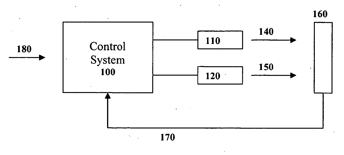
[0019] In another aspect of the present invention there is provided an apparatus for generating light having a desired primary chromaticity having a dominant wavelength, said apparatus comprising: one or more first light-emitting elements for generating first light having a first dominant wavelength, said first dominant wavelength being greater than the dominant wavelength of the desired primary chromaticity; one or more second light-emitting elements for generating second light having a second dominant wavelength, said second dominant wavelength being less than the dominant wavelength of the desired primary chromaticity; a feedback system for monitoring a combination of the first light and the second light, said feedback system for generating feedback signals based thereon; and a control system operatively connected to the feedback system for receiving the feedback signals and for controlling activation of said one or more first light-emitting elements and one or more second light-emitting elements, wherein said control system activates the one or more first light emitting elements and the one or more second light-emitting elements in order that the combination of the first light and the second light creates light having the desired primary chromaticity; wherein the apparatus is adapted for connection to a

Problems solved by technology

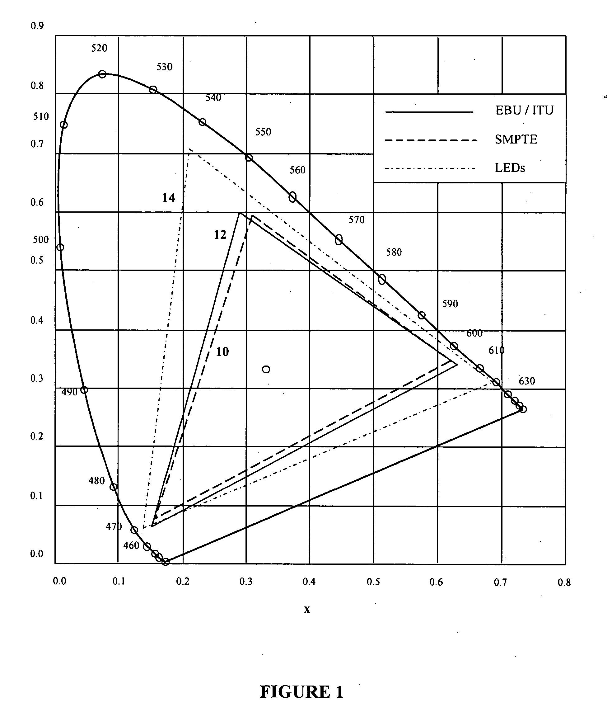
Typical binning criteria for blue and green LEDs are 10 nm intervals for their dominant wavelength, which can result in chromaticity differences greatly in excess of SMPTE and EBU / ITU requirements.
Additional problems that can arise with the use of LEDs for backlighting occur due to temperature dependencies of LEDs.
A further problem with the use of LEDs for backlighting occurs due to spectral broadening with increasing LED junction temperature.
The result of this spectral broadening is a decrease in excitation purity, or saturation of the LED colour and can result in a further change in LED chromaticity.
These objectives may be achieved through careful colour binning of the LEDs by dominant wavelength, although this can be costly as only a small portion of the manufactured LEDs can be used for this purpose.
However, the need to allow for manufacturing tolerances in LED chromaticities and their temperature dependencies tends to restrict the colour gamut that can be achieved.

Method used


Image

  • Backlighting apparatus and method
  • Backlighting apparatus and method
  • Backlighting apparatus and method

Examples


Embodiment Construction

Definitions

[0027] The term “light-emitting element” is used to define any device that emits radiation in any region or combination of regions of the electromagnetic spectrum for example, the visible region, infrared and / or ultraviolet region, when activated by applying a potential difference across it or passing a current through it, for example. Therefore a light-emitting element can have monochromatic, quasi-monochromatic, polychromatic or broadband spectral emission characteristics. Examples of light-emitting elements include semiconductor, organic, or polymer / polymeric light-emitting diodes, optically pumped phosphor coated light-emitting diodes, optically pumped nano-crystal light-emitting diodes or any other similar light-emitting devices as would be readily understood by a worker skilled in the art. Furthermore, the term light-emitting element is used to define the specific device that emits the radiation, for example a LED die, and can equally be used to define a combinati...


PUM


Abstract

The present invention provides a method and apparatus for generating light having a desired chromaticity, wherein two or more light-emitting elements which emit light having a dominant wavelength different from the dominant wavelength of a desired chromaticity can be used to generate light having the desired chromaticity. In particular, the dominant wavelength of one light-emitting element is selected to be greater than that of the dominant wavelength of the desired chromaticity and the dominant wavelength of a second light-emitting element is selected to be less than the dominant wavelength of the desired chromaticity. Two or more light-emitting elements configured in this manner can be employed to generate one of each of the three or more display primaries required for a specific lighting application, for example backlighting of a display panel.

Description

CROSS-REFERENCE TO RELATED PATENT APPLICATIONS [0001] This application is a An application claiming the benefit under 35 USC 119(e) U.S. Application 60 / 688,895, filed Jun. 8, 2005, incorporated herein by reference in its entirety.FIELD OF THE INVENTION [0002] The present invention relates to displays, and more particularly to backlighting of display panels using light-emitting devices. BACKGROUND [0003] The first industry standards for colour video displays were established by the Federal Communications Commission in 1953 through the National Television Standards Committee (NTSC). These standards included specific CIE 1931 xy chromaticities, (i.e., colours) for the red, green, and blue phosphors, or generically the “primaries” used in the cathode ray tubes (CRTs) to ensure that colour reproduction of broadcast images was consistent regardless of the CRT manufacturer. [0004] Phosphor technology for CRT displays has advanced in the half-century since the NTSC specifications were publi...

Claims


Application Information

Patent Timeline
IPC IPC(8): G09G3/32
CPCG02F1/133603G02F1/133609G02F1/133621G09G3/3413H05B33/0869G09G2320/0666G09G2360/145H05B33/0863G09G2320/064H05B45/22H05B45/28
Inventor ASHDOWN, IAN
Owner TIR TECH LP
Learn More