

Pupil detection device and iris authentication apparatus
- Summary
- Abstract
- Description
- Claims
- Application Information
AI Technical Summary
Benefits of technology
Problems solved by technology
Method used
Image

Examples
embodiment
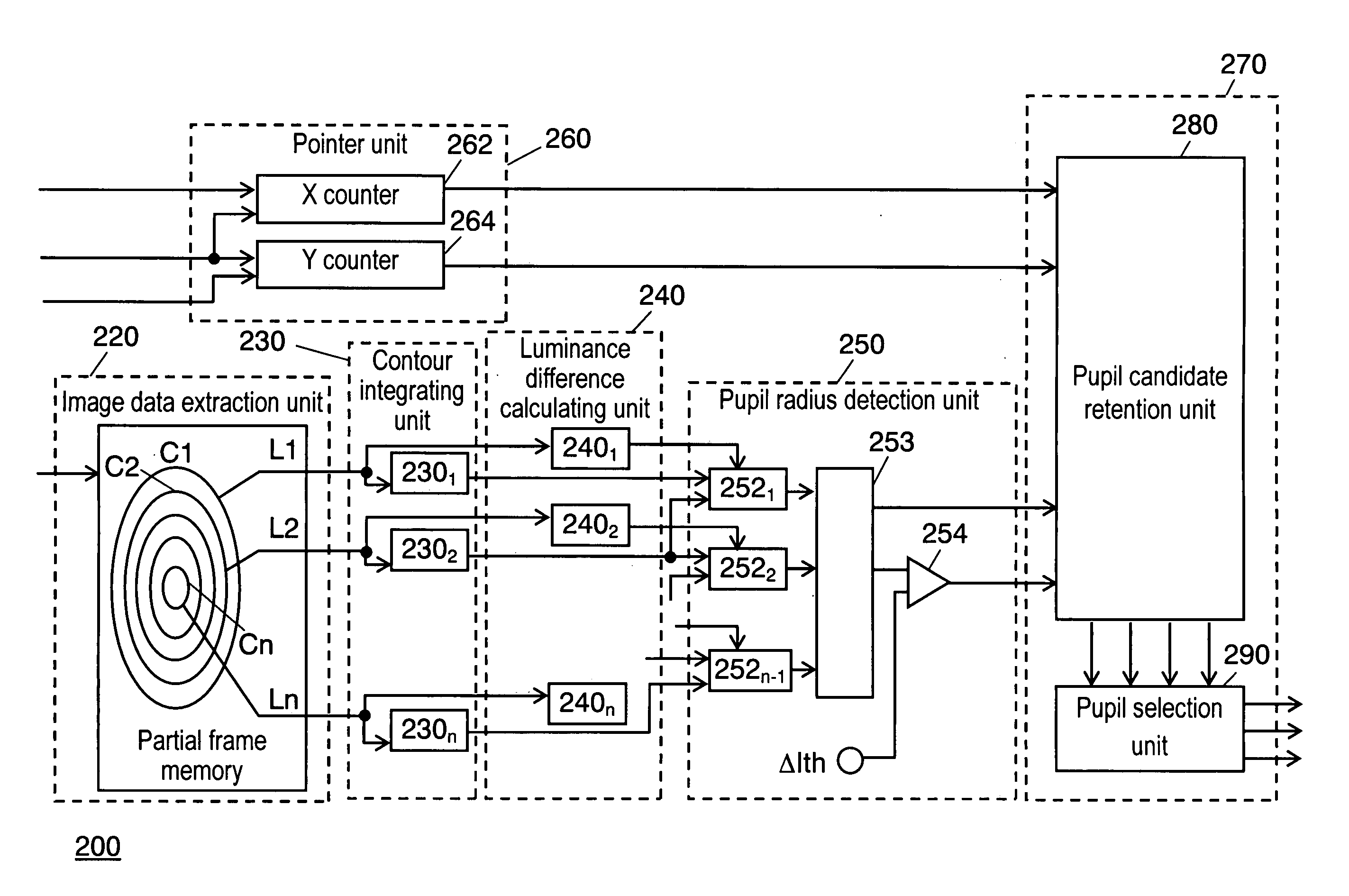
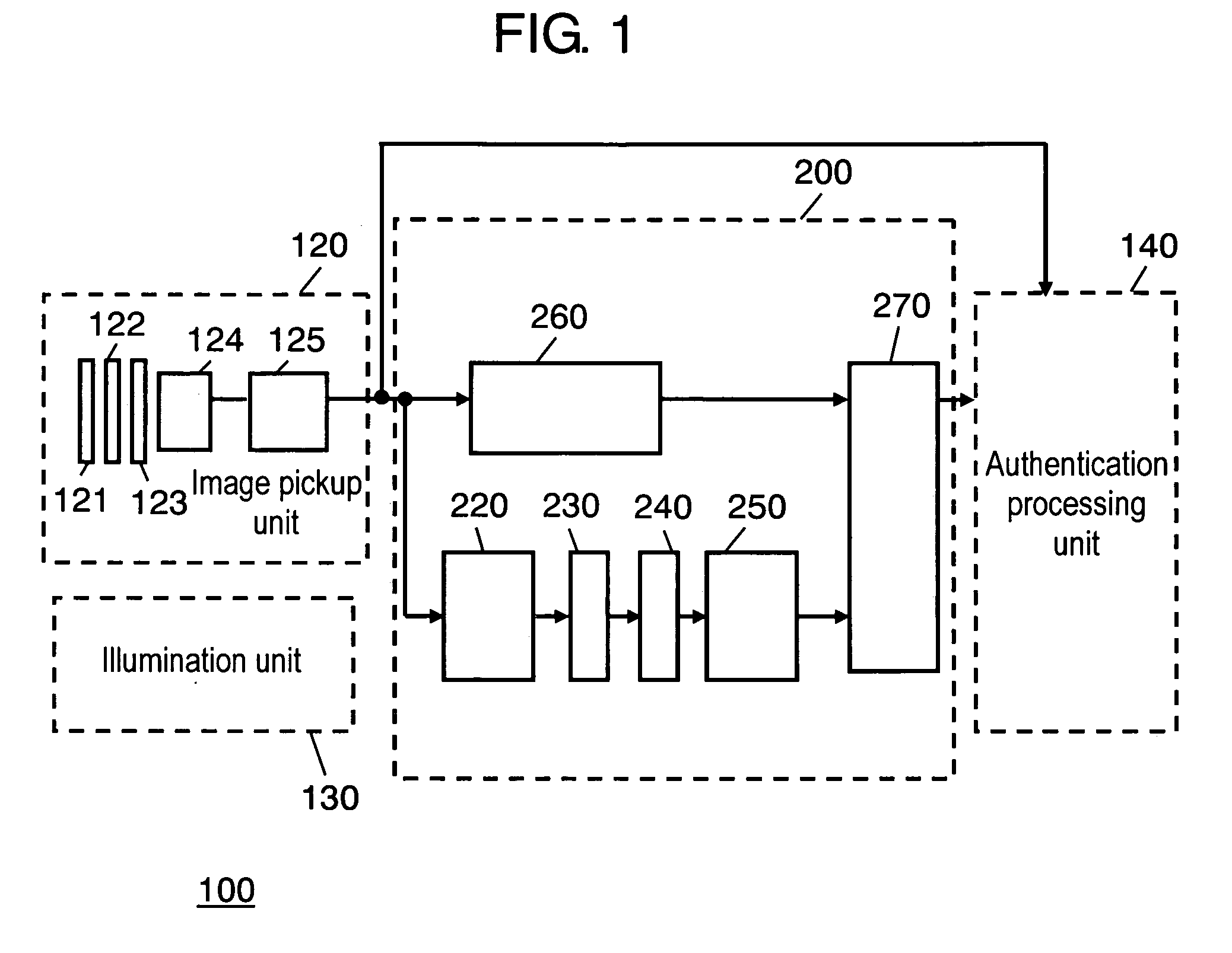
[0048]FIG. 1 is a circuit block diagram of the iris authentication apparatus in which the pupil detection device according to the embodiment of the present invention is employed. In addition to pupil detection device 200, FIG. 1 also illustrates image pickup unit 120, illumination unit 130, and authentication processing unit 140 which are necessary to configure iris authentication apparatus 100.
[0049] Iris authentication apparatus 100 in this embodiment includes image pickup unit 120, pupil detection device 200, authentication processing unit 140, and illumination unit 130. Image pickup unit 120 picks up an eye image of a user. Pupil detection device 200 detects the position of the pupil and the radius thereof from the eye image. Authentication processing unit 140 performs personal authentication by comparing an iris code obtained from the eye image with a registered iris code. Illumination unit 130 irradiates near-infrared ray of a light amount suitable for obtaining the eye image...
PUM
 Abstract
Description
Claims
Application Information