Photonic crystal fibres comprising stress elements

Active Publication Date: 2006-12-28
CRYSTAL FIBRE AS
View PDF2 Cites 27 Cited by
  • Summary
  • Abstract
  • Description
  • Claims
  • Application Information

AI Technical Summary

Benefits of technology

[0110] Use of a photonic crystal fibre according to an aspect of the invention and as described in section ‘A photonic crystal fibre above’

Problems solved by technology

The small core size makes the fibres difficult to work with (for example difficult to couple light to them).
The small core further limits the power handling capacities of the fibres.
It is stated that the methods used to produce birefringence in standard fibres, and thus to produce standard polarisation-preserving fibres, are, in general, not directly suitable for use in photonic-crystal fibre.
Due to the

Method used


Image

  • Photonic crystal fibres comprising stress elements
  • Photonic crystal fibres comprising stress elements
  • Photonic crystal fibres comprising stress elements

Examples


Example

[0145] The figures are schematic and simplified for clarity, and they just show details which are essential to the understanding of the invention, while other details are left out.

MODE(S) FOR CARRYING OUT THE INVENTION

[0146] Optical fibres according to the present invention (termed photonic crystal fibres) have a longitudinal direction and a cross section perpendicular thereto. The cross section of a photonic crystal fibre may vary along its length, but is typically constant. Most references to physical fibre parameters—such as dimensions—and figures of fibre designs refer to or illustrate a photonic crystal fibre cross section.

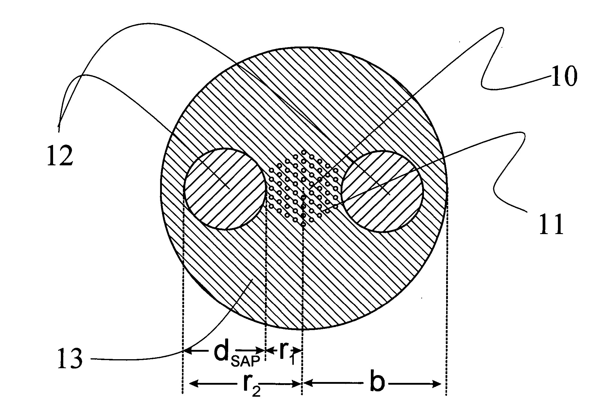
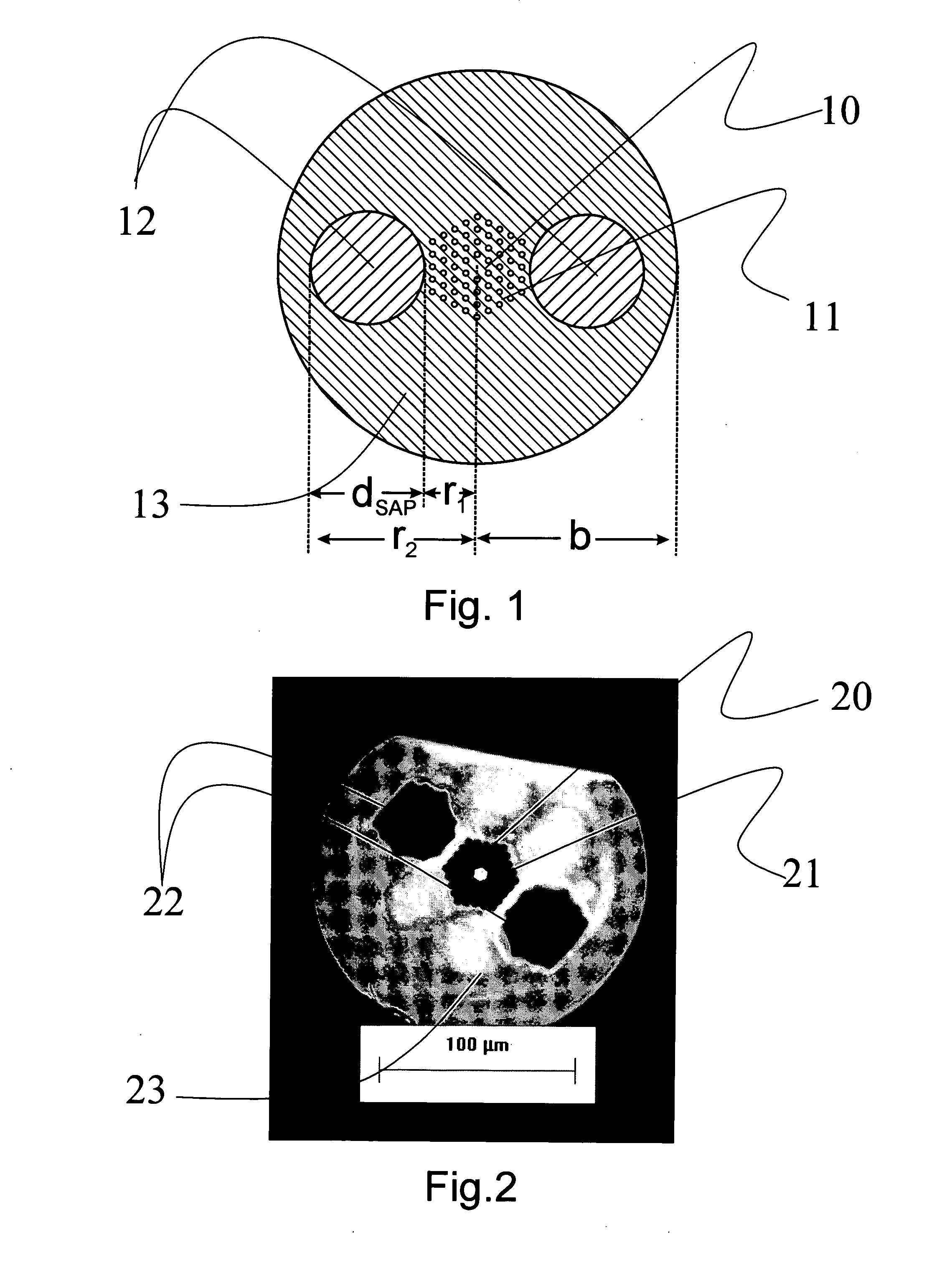
[0147] One preferred embodiment of an optical fibre according to the present invention is shown schematically in FIG. 1. In a cross section, the fibre in FIG. 1 comprises a core region 10, an inner cladding region 11, an outer cladding which comprises two stress applying parts (SAPs) 12 and a background material 13. The core region 10 comprises silica mate...


PUM

PropertyMeasurementUnit
Angleaaaaaaaaaa
Sizeaaaaaaaaaa
Dimensionaaaaaaaaaa

Abstract

A photonic crystal fibre includes a core region for propagating light in a longitudinal direction of the fibre, a cladding region surrounding the core region, the cladding region including micro-structural elements extending in the longitudinal direction. The cladding region further includes at least one stress element having a coefficient of thermal expansion αT,SAP and extending in the longitudinal direction of the photonic crystal fibre, the stress element(s) being located in a cladding background material having a coefficient of thermal expansion αT,cladback different from αT,SAP. The location of the at least one stress element relative to the core region and the micro-structural elements and the coefficients of thermal expansion αT,SAP and αT,cladback are adapted to provide a stress induced birefringence in the core region of the photonic crystal fibre. An article includes a photonic crystal fibre, a method of manufacturing and the use of a photonic crystal fibre are furthermore provided.

Description

CROSS-REFERENCE TO RELATED APPLICATIONS [0001] The present application is a continuation-in-part of PCT / EP2004 / 053601 and claims the priority of Danish patent applications PA 2004 00979, filed Jun. 23, 2004, and PA 2004 01766, filed Nov. 15, 2004, and which further claims the benefit of U.S. provisional application 60 / 530,607, filed on Dec. 19, 2003.TECHNICAL FIELD [0002] The invention relates to stress induced birefringence in photonic crystal fibres. The invention relates specifically to a photonic crystal fibre comprising a core region for propagating light in a longitudinal direction of said photonic crystal fibre, a cladding region surrounding said core region, said cladding region comprising micro-structural elements extending in said longitudinal direction. [0003] The invention furthermore relates to a preform for fabricating a photonic crystal fibre, an article comprising a photonic crystal fibre, and to the use of a photonic crystal fibre. [0004] The invention may e.g. be u...

Claims


Application Information

Patent Timeline
IPC IPC(8): G02B6/02G02B6/024C03B37/012G02B6/10
CPCC03B37/01217C03B37/0122C03B2203/14C03B2203/31C03B2203/42G02B6/02314G02B6/105G02B6/02352G02B6/02357G02B6/02361G02B6/02366G02B6/024G02B6/02347
Inventor FOLKENBERG, JACOB RIISNIELSEN, MARTIN DYBENDALMORTENSEN, NIELS ASGER
Owner CRYSTAL FIBRE AS
Why Eureka
Try Eureka