
Cartridge foam insert for foam generating and injecting apparatus

a technology of foam generating and injecting apparatus, which is applied in the directions of transportation and packaging, mixing, chemistry apparatus and processes, etc., can solve the problems of insufficient surface area of the material for effective agitation, limited foaming material used in the foaming chamber of the spray gun, and time-consuming collection and cleaning of loose items

Inactive Publication Date: 2006-12-28
CORE FOAM
View PDF2 Cites 18 Cited by
  • Summary
  • Abstract
  • Description
  • Claims
  • Application Information

AI Technical Summary

Benefits of technology

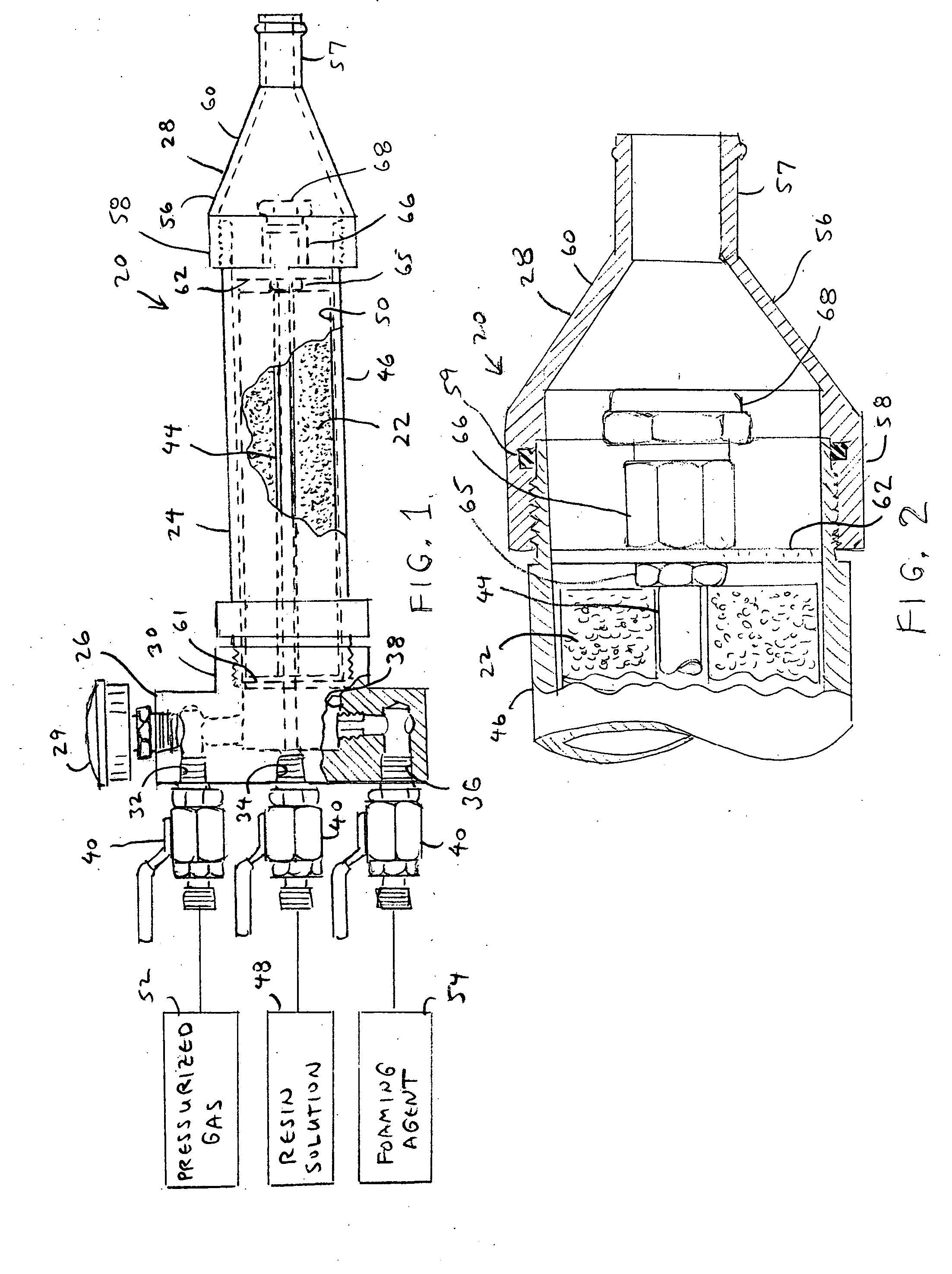
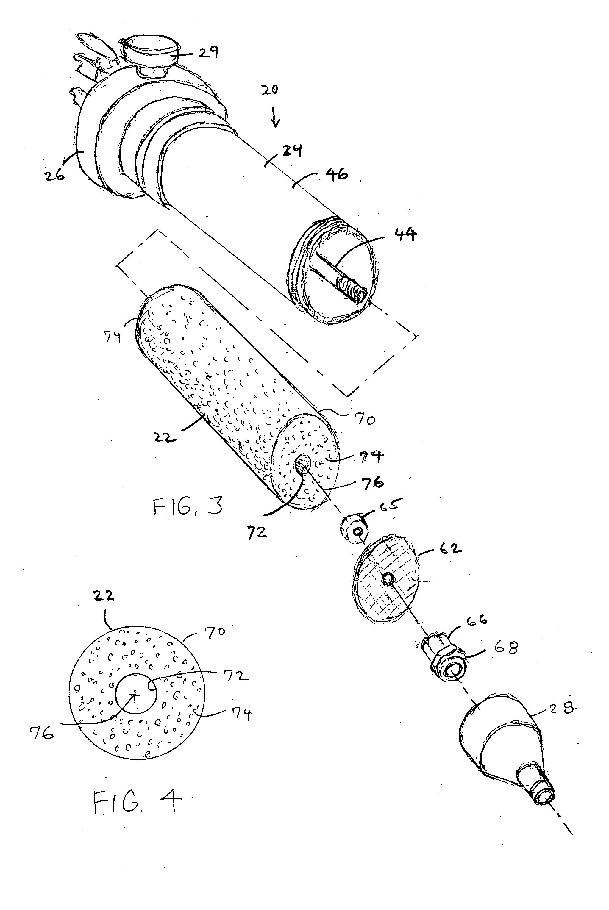
[0011] The filler material includes a body of polyurethane foam which is adapted to be accepted by and substantially fill the interior of the foaming chamber for enhancing the blend of the mixable foam-producing ingredients as the mixable foam-producing ingredients are conducted through the foaming chamber.

Problems solved by technology

Heretofore, filler material used within the foaming chamber of a spray gun has been limited in that it is either comprised of loose items (e.g. glass beads) or is comprised of compressible material (e.g. steel wool) which is susceptible of being packed within the foaming chamber either too tightly or too loosely.
If, for example, the filler material is comprised of loose items, such as glass beads, the servicing of the spray gun—which commonly requires an emptying of the foaming chamber—also requires a time-consuming collection and cleaning of the loose items and subsequent re-introduction of the loose items within the foaming chamber.
Furthermore, if the filler material is packed too tightly, the material might not permit the desired flow of foaming catalyst and gas through the foaming chamber, and if the filler material is packed too loosely, the material could provide an insufficient amount of surface area to effectively agitate the flow of foaming catalyst and gas through the foaming chamber.

Method used


Image

  • Cartridge foam insert for foam generating and injecting apparatus
  • Cartridge foam insert for foam generating and injecting apparatus

Examples


Embodiment Construction

[0016] Turning now to the drawings in greater detail and considering first FIG. 1, there is illustrated a foam generating and injecting apparatus (hereinafter referred to as a spray gun), generally indicated 20, and a cartridge foam insert 22 shown positioned within the spray gun 20. The spray gun 20 is adapted to receive three foam-producing ingredients, namely, a pressurized gas (e.g. air), a liquid solution of resin, and a liquid foaming catalyst, used to generate a foamed polymer resin within the gun 20 for discharge from one end thereof. As will be apparent herein, the spray gun 20 includes a foaming chamber within which two of the foam-producing ingredients (i.e. a foaming catalyst and a compressed gas) are mixed together to produce a foamy mixture prior to the introduction of the foamy mixture to the third foam-producing ingredient (i.e. a resin) within the gun 20, and the foam insert 22 is positioned within the foaming chamber to enhance the agitation and subsequent blend of...


PUM

PropertyMeasurementUnit
densityaaaaaaaaaa
densityaaaaaaaaaa
densityaaaaaaaaaa

Abstract

A filler material in the form of a cartridge insert is positionable within an apparatus for generating and injecting a foamed polymeric resin formed by the mixture of a plurality of foam-producing ingredients wherein the apparatus includes an elongate foaming chamber having an interior through which two mixable foam-producing ingredients are conducted. The filler material includes a body of polyurethane foam which is adapted to be accepted by and substantially fill the interior of the foaming chamber for enhancing the blend of the mixable foam-producing ingredients as the mixable foam-producing ingredients are conducted through the foaming chamber. Preferably, the polyurethane foam of the body is a polyether polyurethane foam, possesses an Indentation Force Deflection value which is at least as great as 30 pounds per 50 square inches (30 lbs / 50 in2) and possesses a density which is between within the range of between 1.0 lbs / ft3 and 5.0 lbs / ft3.

Description

BACKGROUND OF THE INVENTION [0001] This invention relates generally to apparatus for generating and injecting a foamed polymeric resin produced with foam-producing ingredients delivered to the apparatus and relates, more particularly, to componentry within such apparatus for enhancing the blend of foam-producing ingredients with one another as the foam-producing ingredients are conducted through the apparatus. Foamed polymeric resins have been found to be particularly well-suited for use as a thermal and / or acoustical insulation. [0002] The apparatus with which this invention is concerned is in the form of an elongated spray gun having a manifold section at one of the gun through which foam-producing ingredients are introduced to the gun and a nozzle section at the opposite end of the gun through which the generated foam is discharged from the gun. The foam-producing ingredients used to generate a foam within the gun include a liquid solution of resin, a liquid solution of foaming c...

Claims


Application Information

Patent Timeline
Patent Type & Authority Applications(United States)
IPC IPC(8): C08G18/00
CPCB01F5/045B01F5/0698C08L75/08B29B7/7438B29C44/3446B01F2015/0221B01F25/313B01F25/45243B01F35/715
Inventor PORTER, RICHARD A.
Owner CORE FOAM
Learn More