
Energy efficiency improvements for turbomachinery

A technology of energy efficiency and operating capability, applied in the field of Newtonian fluid flow aerodynamic/hydrodynamic processing devices, to achieve the effect of reducing resistance, improving existing technology, and reducing absolute resistance

Inactive Publication Date: 2016-02-03
彼得·艾瑞兰德 +1
View PDF36 Cites 24 Cited by
  • Summary
  • Abstract
  • Description
  • Claims
  • Application Information

AI Technical Summary

Problems solved by technology

In cruise these vortex generators are at minimum angle of attack, since in the vortex they are not needed, so there is less form drag, but there is always more form and surface drag

Method used


Image

  • Energy efficiency improvements for turbomachinery
  • Energy efficiency improvements for turbomachinery
  • Energy efficiency improvements for turbomachinery

Examples


Embodiment Construction

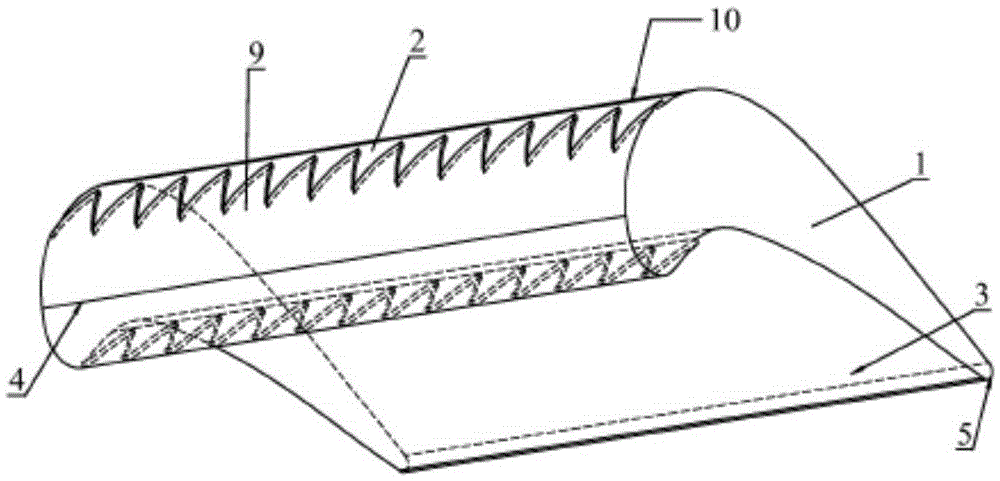
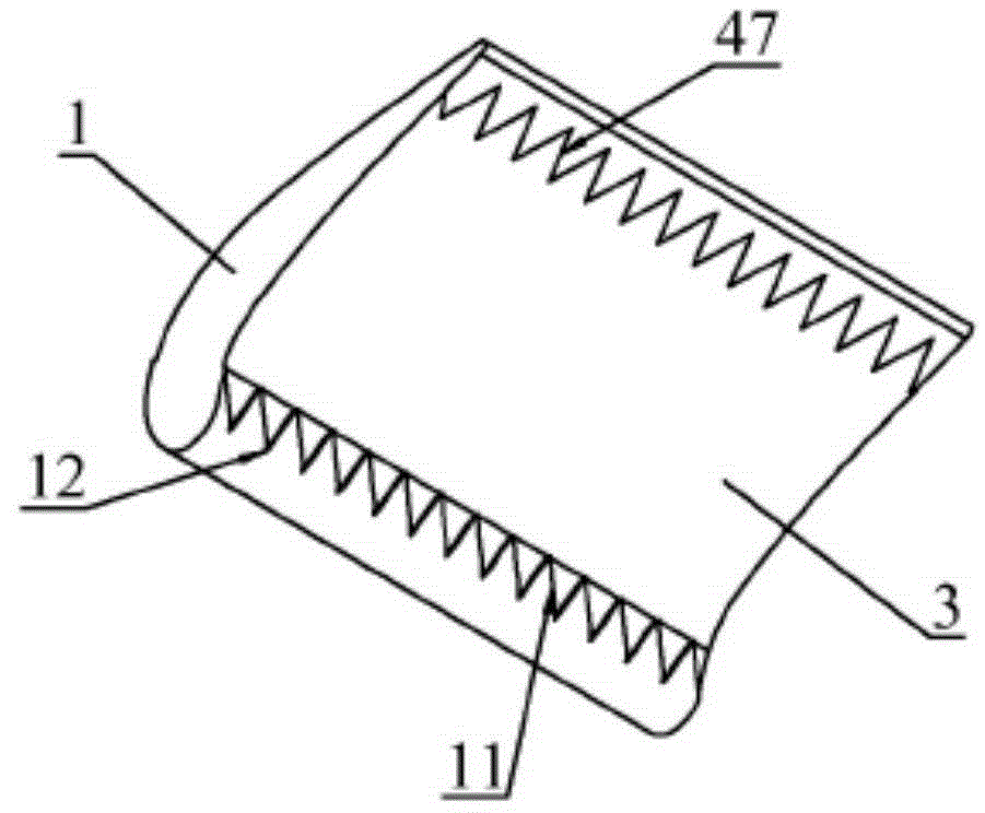
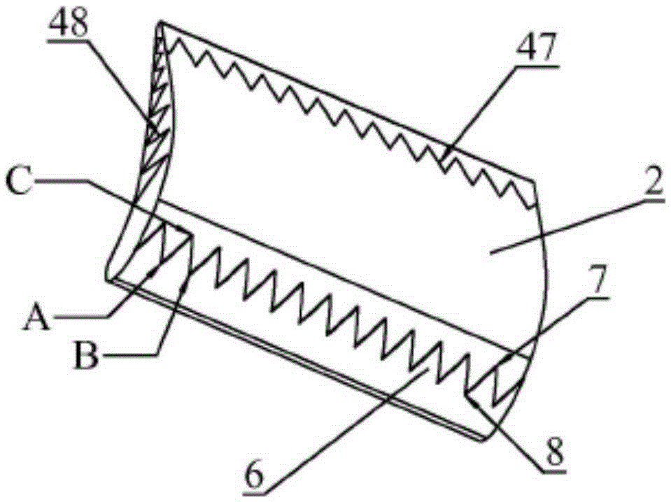
[0081] The best mode for carrying out the invention is an example of a turbofan jet engine, which can teach many typical aspects and methods of application, which can be achieved by applying properly configured integrated conformal vortex generators. The turbofan engine provides a considerable number of examples of useful integrated application of conformal vortex generators because it employs extensive hydrodynamic surface treatment of the flow of Newtonian fluids to produce beneficial work and effects. This example is only one form of a fluid flow machine that uses a gas as the working fluid, but most conformal vortex generator methods can be easily adapted to use liquid or mixed phase Newtonian physical fluids and obtain similar improvements, such as Many useful examples of drag and separation / cavitation reduction are achieved by scaling; velocity, pressure, Reynolds number, fluid phase (gas / liquid state transition) and flow viscosity.

[0082] Figure 1a Callout 1 describ...


PUM


Abstract

A method and apparatus are disclosed that allow Conformal Vortex Generator art to improve energy efficiency and control capabilities at many points in a turbomachine or device processing aero / hydrodynamic Newtonian fluid-flows.

Description

[0001] Cross reference related applications: [0002] This application is the continuation of the patent application number US2011 / 0006165A1, the filing date is July 8, 2010, and the continuation of the application in the U.S. national phase is made by the U.S. Provisional Patent Application No. A derived non-provisional application, also International Application PCT / IB2010 / 001885 filed on July 9, 2010. technical field [0003] The invention belongs to the field of Newtonian fluid flow aerodynamic / hydrodynamic processing devices, and utilizes the hydrodynamic structure of a novel conformal vortex generator (CVG) to improve its energy efficiency and / or performance. This novel application of typical embedded or integrated CVGs is applicable to many places and tasks, e.g., exciter disks, park vane cascades and flow surfaces of dynamic turbomachinery, such as mobile turbine engines, static power generation turbines, helicopters , wings and other Newtonian fluid flow applications...

Claims


Application Information

Patent Timeline
Patent Type & Authority Applications(China)
IPC IPC(8): B64C23/06F04D29/38
CPCB64C23/06F01D5/145F04D29/681F04D29/684F05D2240/121F05D2240/122F05D2240/303F05D2240/304F05D2250/183Y02T50/10Y02T50/60F01D5/14F04D29/38F15D1/06F23R3/14
Inventor 彼得·艾瑞兰德安东尼·艾瑞兰德
Owner 彼得·艾瑞兰德
Learn More