Device for applying adhesive to a workpiece

a technology for workpieces and adhesives, applied in the direction of coatings, programmed manipulators, programme control, etc., can solve the problems of time-consuming and substantial calibration efforts, and achieve the effect of rapid defect recognition and correction

Inactive Publication Date: 2007-01-04
SCHUCKER JOSEF
View PDF5 Cites 32 Cited by
  • Summary
  • Abstract
  • Description
  • Claims
  • Application Information

AI Technical Summary

Benefits of technology

[0008] The inventive solution is based upon the idea, that the adhesive strip can be observed optically or can be scanned in the manner of a distance profile immediately after its application upon the workpiece, in order in the case of unacceptable deviations from a reference image or reference profile to initiate a recalibration. In order to accomplish this, it is proposed in accordance with the invention to provide at least one camera unit, preferably a video camera or thermal (infrared) camera, on the nozzle head or on the associated robotic element, with its lens directed towards the spray beam or the adhesive strip, the camera output connected to an image evaluation unit. In order to maintain the illumination as constant as possible, it is advantageous to provide a lighting or illumination unit on the nozzle head or on the associated robotic element.
[0015] Preferably the image evaluation unit is comprised of a control computer and image evaluation software. The image evaluation unit or the control computer could preferably be networked with an external computer via an online network. The external computer could on the other hand be networked, preferably via the online network, with the control unit. By this means an online monitoring of the adhesive robot as well as the adaptation of the actuation and control parameters becomes possible from an external monitoring location such as, for example, using the internet. The seamless and continuous image presentation makes possible besides this a rapid defect recognition and correction.

Problems solved by technology

In the case that the compressed gas supply is made viscosity dependent, this involves a control technical measure which requires a substantial calibration effort.
Above all in the case of the change of application parameters, in the case of changing the robot program or in the case of changing the adhesive or the workpiece surface, recalibrations are necessary, which can be quite time consuming.

Method used


Image

  • Device for applying adhesive to a workpiece
  • Device for applying adhesive to a workpiece
  • Device for applying adhesive to a workpiece

Examples


Embodiment Construction

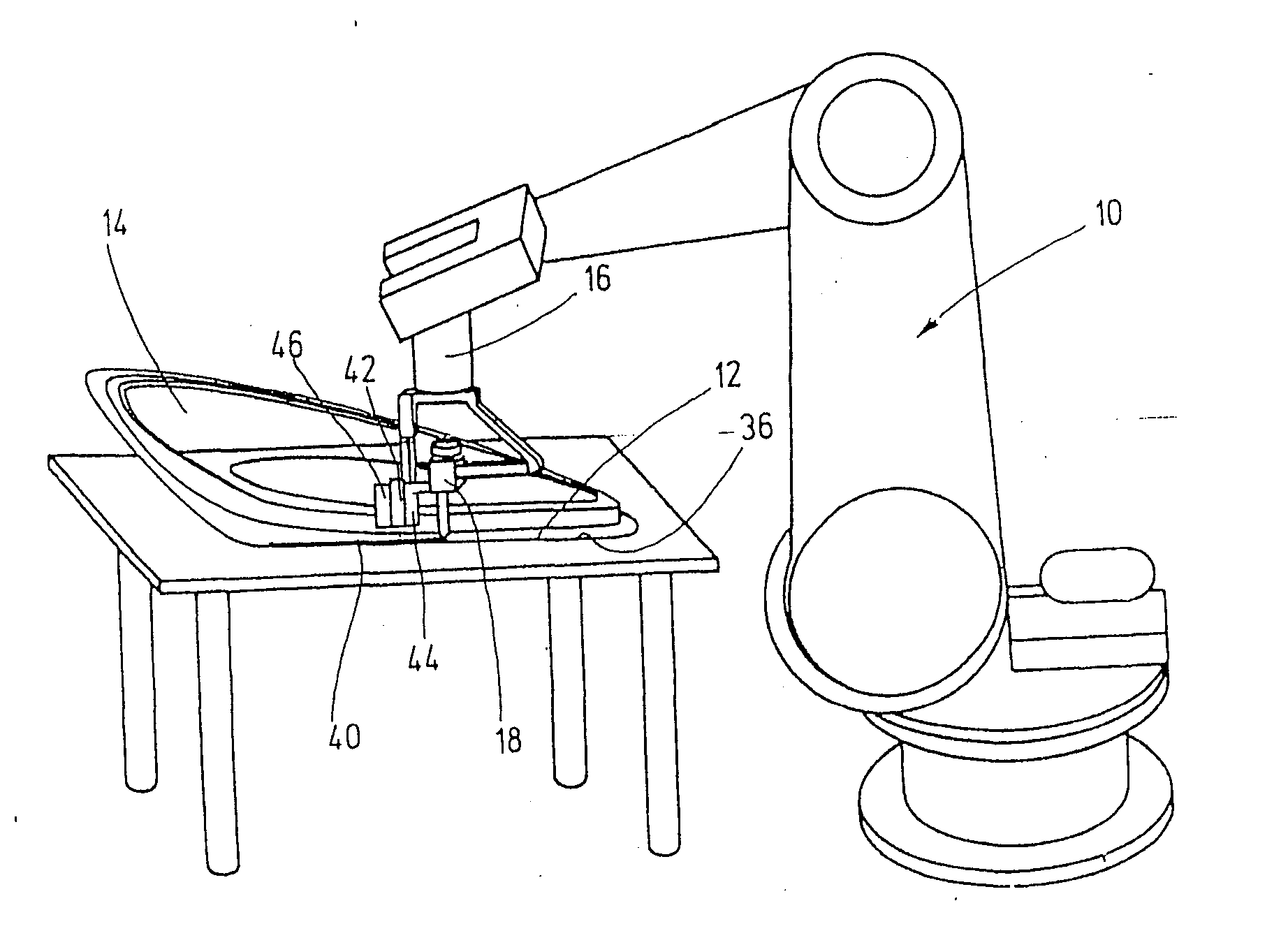
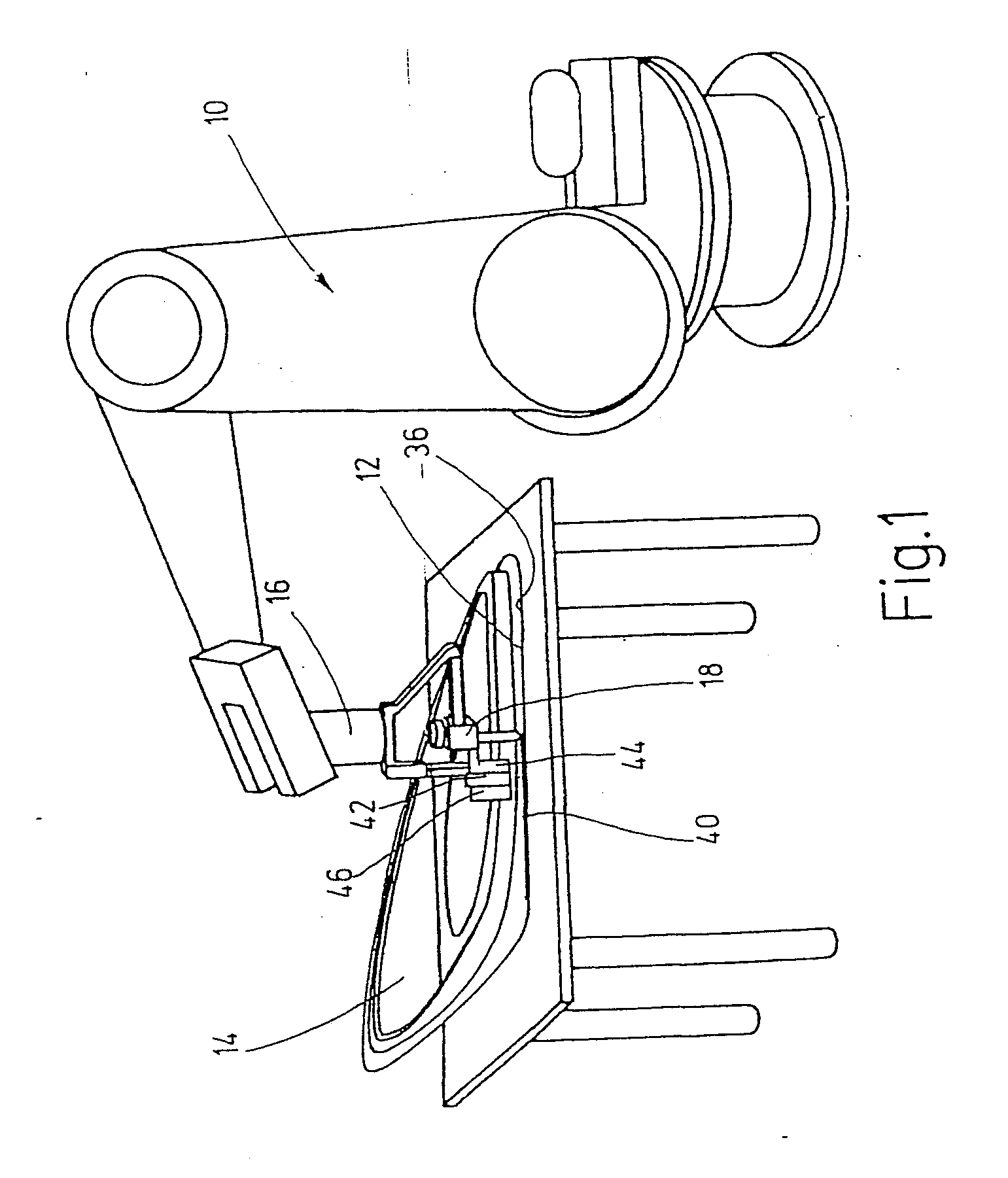
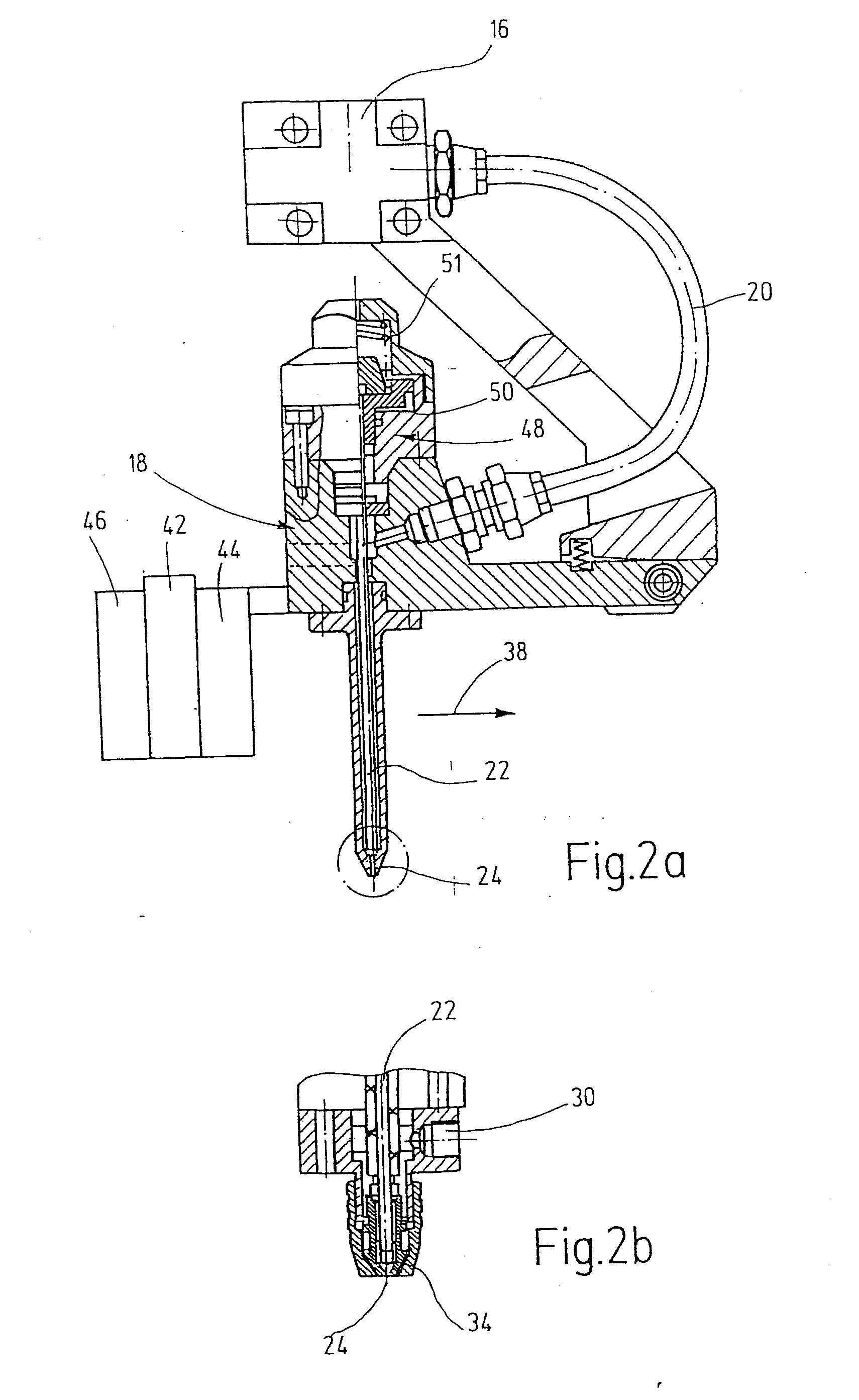
[0022] The robot 10 shown in the figure is designed for application of adhesive for sealing of edge beads or flange welds 12 of workpieces 14, here parts for passenger vehicles. The robot carries for this purpose on its end element 16 a nozzle head 18, which is supplied with a pasty adhesive via a flexible hose 20 and includes an application nozzle 24 closeable via a valve needle 22. The actuation of the valve needle 22 occurs via a cylinder-piston arrangement 48, of which the piston 50, when in the open position, is slid upward pneumatically by the robot control against the force of a closing spring 51, and in the closed position is slid downward under the influence of the closing spring 51. In the shown embodiment the nozzle head 18 is a cyclone spray head, wherein the adhesive thread 28 is emitted out of the application nozzle 24, which thread is deflected and whirled with the aid of pressurized gas, such that a strip-like laid-down partially open adhesive strip 40 of defined bre...


PUM


Abstract

An adhesive robot, comprising a device for applying adhesive to a workpiece. The adhesive robot has a nozzle head (18), which has an application nozzle (24) and can be supplied with a pressurized viscous adhesive, the nozzle head (18) and the workpiece (14) being displaceable in relation to one another. The adhesive which is issued from the application nozzle (24) in a spray jet (28) is applied to a workpiece (14) along a predefined line of application (36) in the form of a strip of adhesive (40). To facilitate the adjustment and re-calibration process, the system comprises at least one camera unit (42), which is located on the nozzle head (18) and whose leans is directed towards the spray jet (28) or the adhesive strip (40). The output of said camera unit is connected to an image evaluation unit (45). The image data (40) recorded by the camera unit (42) is buffered and compared with predetermined image values (40). The decisive control parameters for the system can be calibrated and tracked either automatically or by remote control, on the basis of deviations in the image data that have been determined along the line of application (36).

Description

CROSS-REFERENCE TO RELATED APPLICATIONS [0001] This application is a continuation application of U.S. patent application Ser. No. 10 / 381,950, filed on Jun. 30, 2003, now U.S. Pat. No. ______, which is incorporated herein by reference in its entirety. No new matter is contained in this continuation application.BACKGROUND OF THE INVENTION [0002] 1. Field of the Invention [0003] The invention concerns a device for applying adhesive to a workpiece, the device including a nozzle head that can be supplied with viscous adhesive under pressure and an application nozzle, wherein the nozzle head and the workpiece are moveable relative to each other via robotic means, such that the adhesive emitted from the application nozzle, preferably in the manner of a spray jet, is applied to the workpiece in the form of an adhesive strip along a predefined line of application. In the following the term “adhesive” is intended to include other viscous materials, such as insulation, which can be applied to ...

Claims


Application Information

Patent Timeline
Patent Type & Authority Applications(United States)
IPC IPC(8): B05C11/00B05B1/34B05B12/00B05C5/00B05C5/02B25J9/16B25J19/02G05B19/418
CPCB05C5/0216B25J9/1684B25J9/1697B25J19/02G05B2219/45238G05B19/4189G05B2219/37048G05B2219/37217G05B2219/45065B25J19/023Y02P90/02
Inventor SCHUCKER, JOSEF
Owner SCHUCKER JOSEF
Why Eureka
Try Eureka