Oil cooler

Inactive Publication Date: 2007-01-04
CALSONIC KANSEI CORP
View PDF15 Cites 27 Cited by
  • Summary
  • Abstract
  • Description
  • Claims
  • Application Information

AI Technical Summary

Benefits of technology

[0028] Therefore, its manufacturing

Problems solved by technology

This conventional oil cooler, however, encounters the following problems in production management, causing high manufacturing costs and others.
Specifically, it takes some trouble with tightening torque management when screwing a nut to the pipe connecter to fix the connecting pipe, and seal-member extrusion-or-intrusion preventing management.
In addition, various diameter types of pipe connectors are required so as to fit different diameters of the connecting pipes, which increases its design and manufacturing costs.
Further, the heat exchange part and the radiator tank are fixed with each other by using an addition

Method used


Image

  • Oil cooler
  • Oil cooler
  • Oil cooler

Examples


Embodiment Construction

[0051] Throughout the following detailed description, similar reference characters and numbers refer to similar elements in all figures of the drawings, and their descriptions are omitted for eliminating duplication.

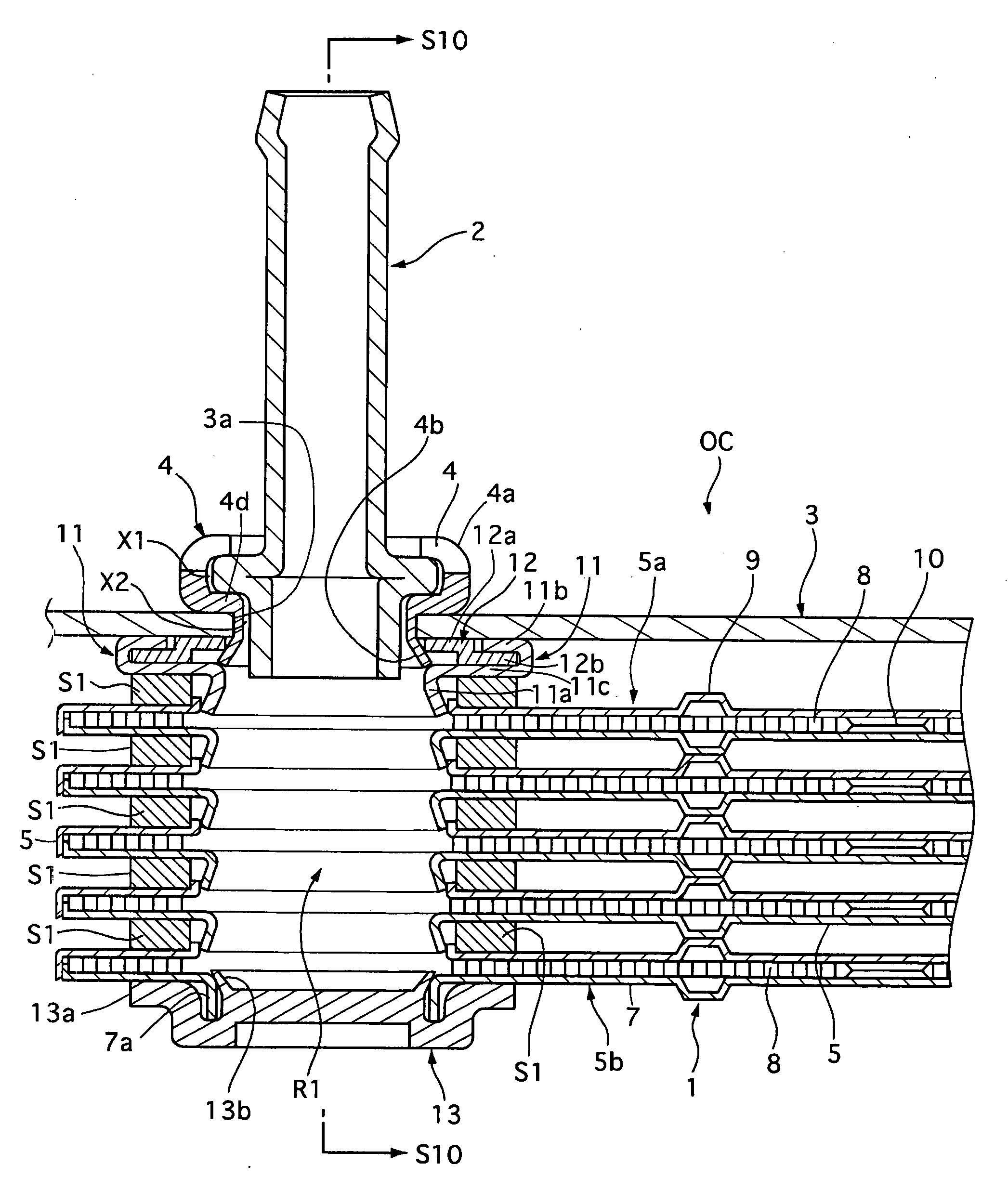
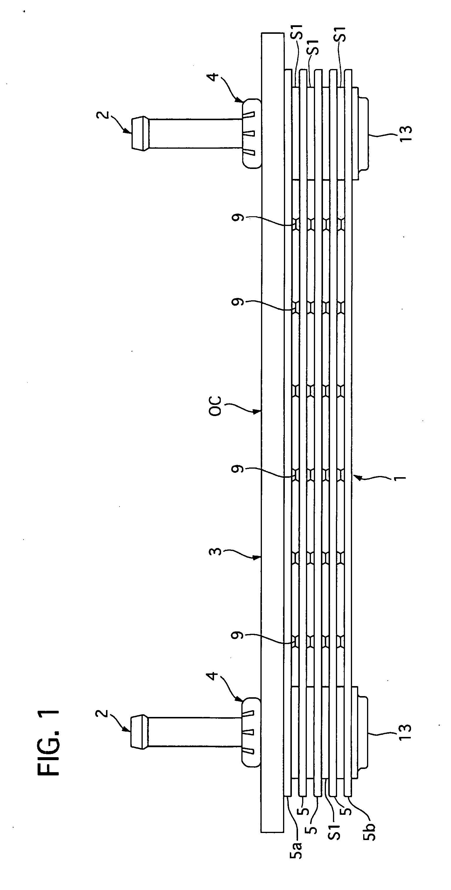
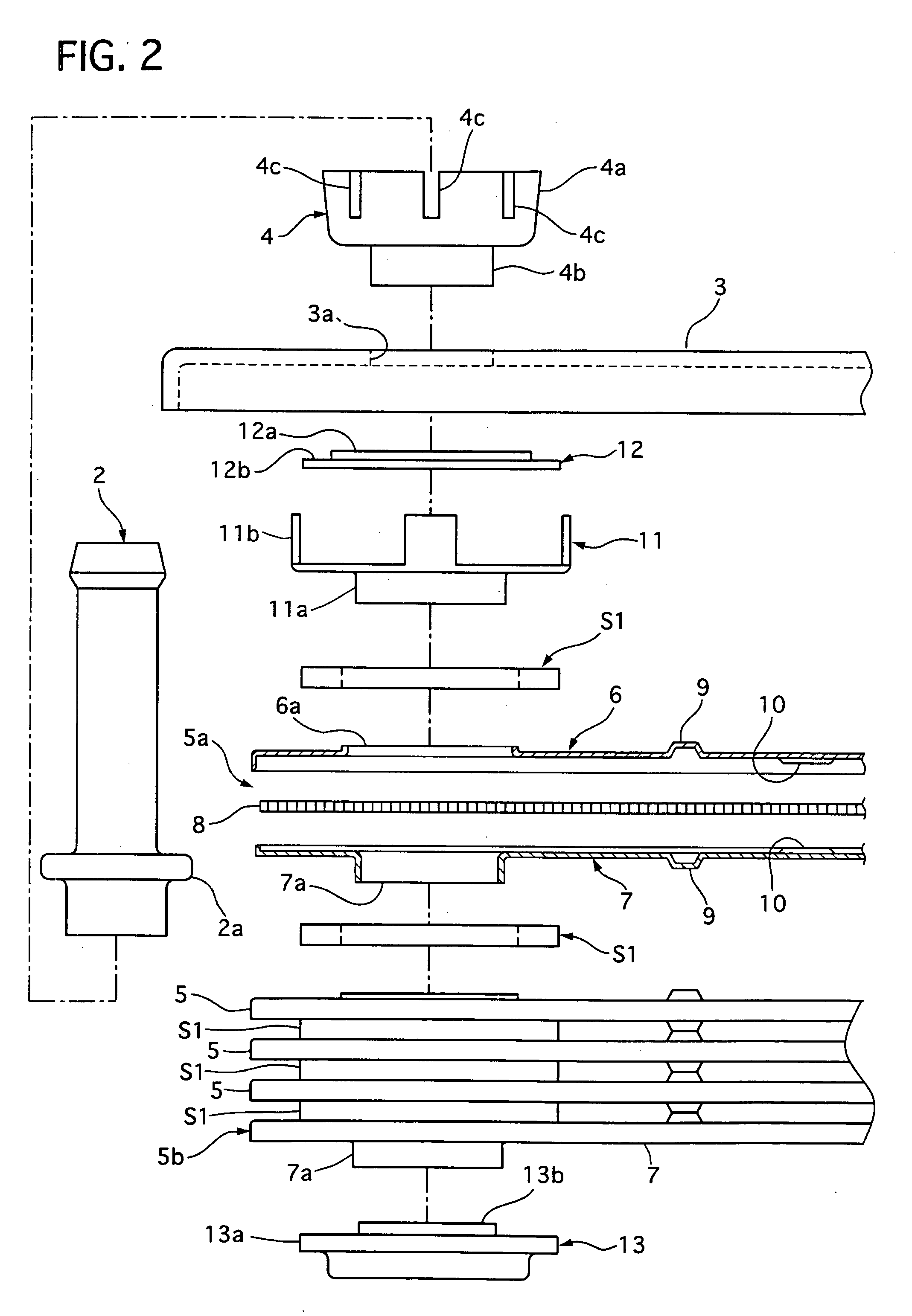
[0052] Referring to FIGS. 1 to 3, there is shown an oil cooler OC of an embodiment according to the present invention. FIGS. 2 and 3 is sectional front views showing only a left part of the oil cooler OC, and its left and right parts are symmetrical with respect to each other.

[0053] The oil cooler OC is used for cooling oil of an automatic transmission mounted on a motor vehicle for example, and arranged in a lower radiator tank of a not-shown radiator, so that radiator coolant flows around the oil cooler OC to draw heat from the oil after the radiator coolant is cooled by a radiator core of the radiator.

[0054] The oil cooler OC includes a heat exchange part 1 having a plurality of elements 5a, 5 and 5b fluidically connected by left and right communicating passages R1...


PUM


Abstract

An oil cooler is contained in a radiator tank. It includes a connecting pipe having an enlarged diameter portion, a heat exchange part including elements and a communicating passage fluidically communicating the elements, and a pipe connector. The pipe connector has a first retaining portion seated on one side of a wall portion of the radiator tank to contain and fix at least a part of the enlarged diameter portion of the connecting pipe by caulking, and a second retaining portion inserted through a through-hole of the wall portion and an one end portion of the communicating passage to fix the heat exchanger part and the wall portion at the other side of the wall portion by caulking.

Description

BACKGROUND OF THE INVENTION [0001] 1. Field of the Invention [0002] The present invention relates to an oil cooler that is contained in a radiator tank and used for a motor vehicle or the like. [0003] 2. Description of the Related Art [0004] A conventional oil cooler contained in a radiator tank is disclosed in Japanese patents laying-open publication No. 2001-272195, No. 2002-195783, and No. (Tokkaihei) 11-211378, and Japanese Patent No. 3245739. The oil cooler is provided with a heat exchange part for cooling oil flowing therethrough, two connecting pipes each for connecting a top portion of a communicating passage of the heat exchange part and a vehicle-side device, and two patch plates each for fluidically plugging a bottom portion of the communicating passage. [0005] The heat exchange part includes a plurality of elements, each of which has coupled shell members containing an inner fin and are piled up. The two communicating passages are formed vertically at the both side porti...

Claims


Application Information

Patent Timeline
IPC IPC(8): B60H1/00
CPCF28D9/0043F28F9/0234F28F9/0246Y10S165/916F28F9/165F28F2240/00F28F9/0248
Inventor OZAWA, TATSUHIRONAKAJIMA, SHIROMATSUDAIRA, NORIMITSUNAKAKOMI, TAKAHIROMIYASAKA, SHINICHIONUKI, HISASHI
Owner CALSONIC KANSEI CORP
Why Eureka
Try Eureka