Model railroad control and sound systems

a model railroad and control system technology, applied in the field of model railroad control systems, can solve the problems of ac powered trains that require greater power, produce more electrical noise, and difficult to direct transmission of electrical control signals down the track of ac powered trains, and achieve the effect of reducing the difficulty of dc powered trains to achieve direct transmission of electrical control signals

Inactive Publication Date: 2007-01-04
QSINDS
View PDF8 Cites 56 Cited by
  • Summary
  • Abstract
  • Description
  • Claims
  • Application Information

AI Technical Summary

Benefits of technology

[0018] According to yet another embodiment, a model railroad system includes a power pack having a throttle to apply a power signal to a set of train tracks. A switching device is in electrical communication with the power pack and the train tracks to reverse a polarity of the power signal on the train tracks. The system includes an input and a processor in electrical communication with the switching device. The processor receives a command from the input to produce, by control of the switching device, a digital command having a series of sequential reversals in the polarity of the power signal. The switching device may include, but is not limited to, a relay or an active bridge circuit.

Problems solved by technology

A number of viable and commercial command control systems were introduced in the 1980's but serviced a small segment of the market due to its technological complexities and confusion over the variety of methods being sold.
Because of their universal AC / DC motors and power pickup methods, AC powered trains require greater power and produce more electrical noise than the more efficient DC powered trains introduced in the 1950's.
For this reason, direct transmission of electrical control signals down the track for AC powered trains has been more difficult than for DC powered trains.
Although NMRA DCC has been tried with AC three-rail tracks, it has not proved very reliable or popular.
Because a model railroad track is used for both power and signaling, the power movement down the track generally creates an electrically noisy and low impedance environment that can make signaling back to the base station difficult.
However, to date, no bi-directional communication system has been proposed for analog DC or conventional AC operation other than sending BEMF voltage from the locomotive's motor back to the controller.
Standard DC powered trains were even more limited in operation than AC powered trains.

Method used


Image

  • Model railroad control and sound systems
  • Model railroad control and sound systems
  • Model railroad control and sound systems

Examples


Embodiment Construction

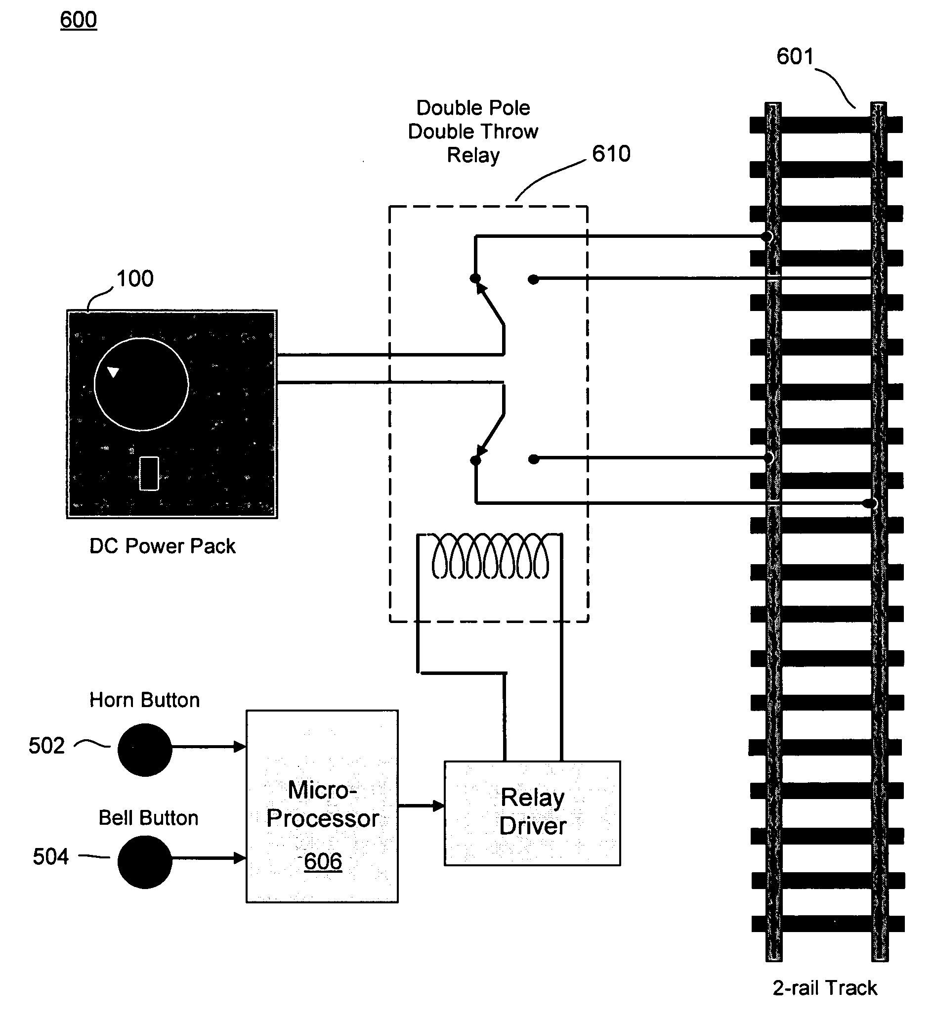
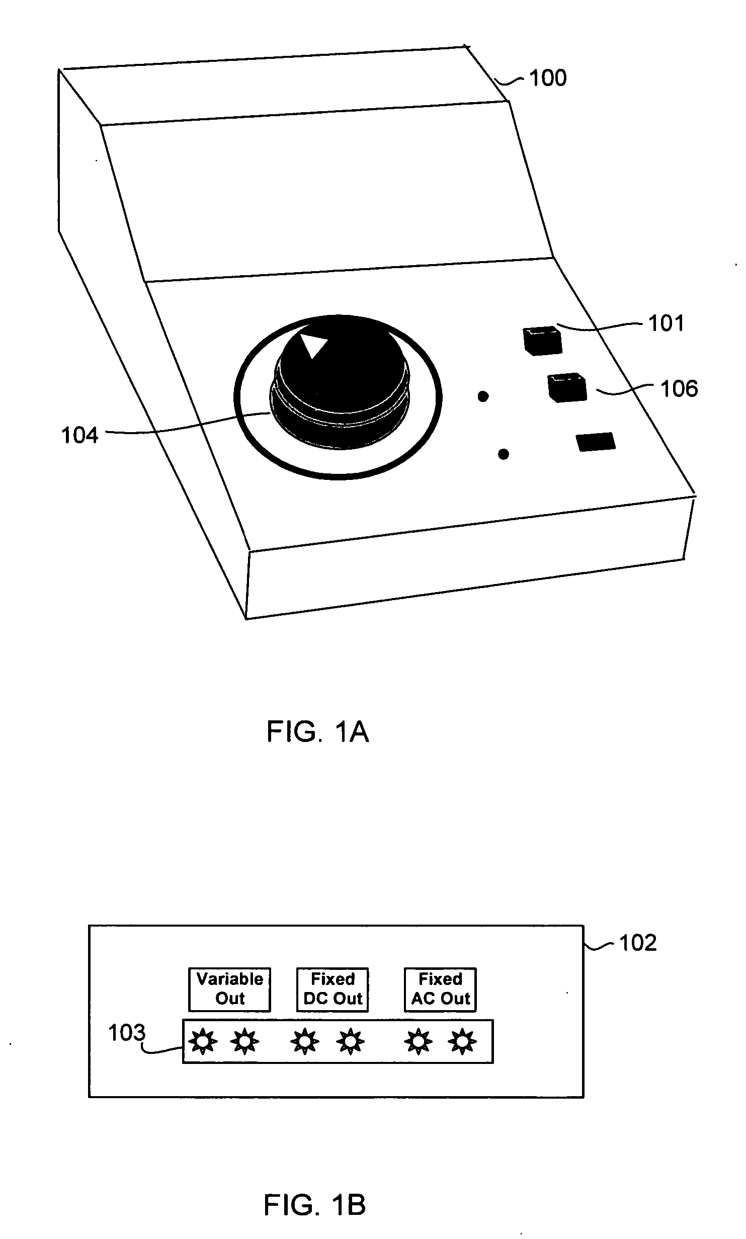
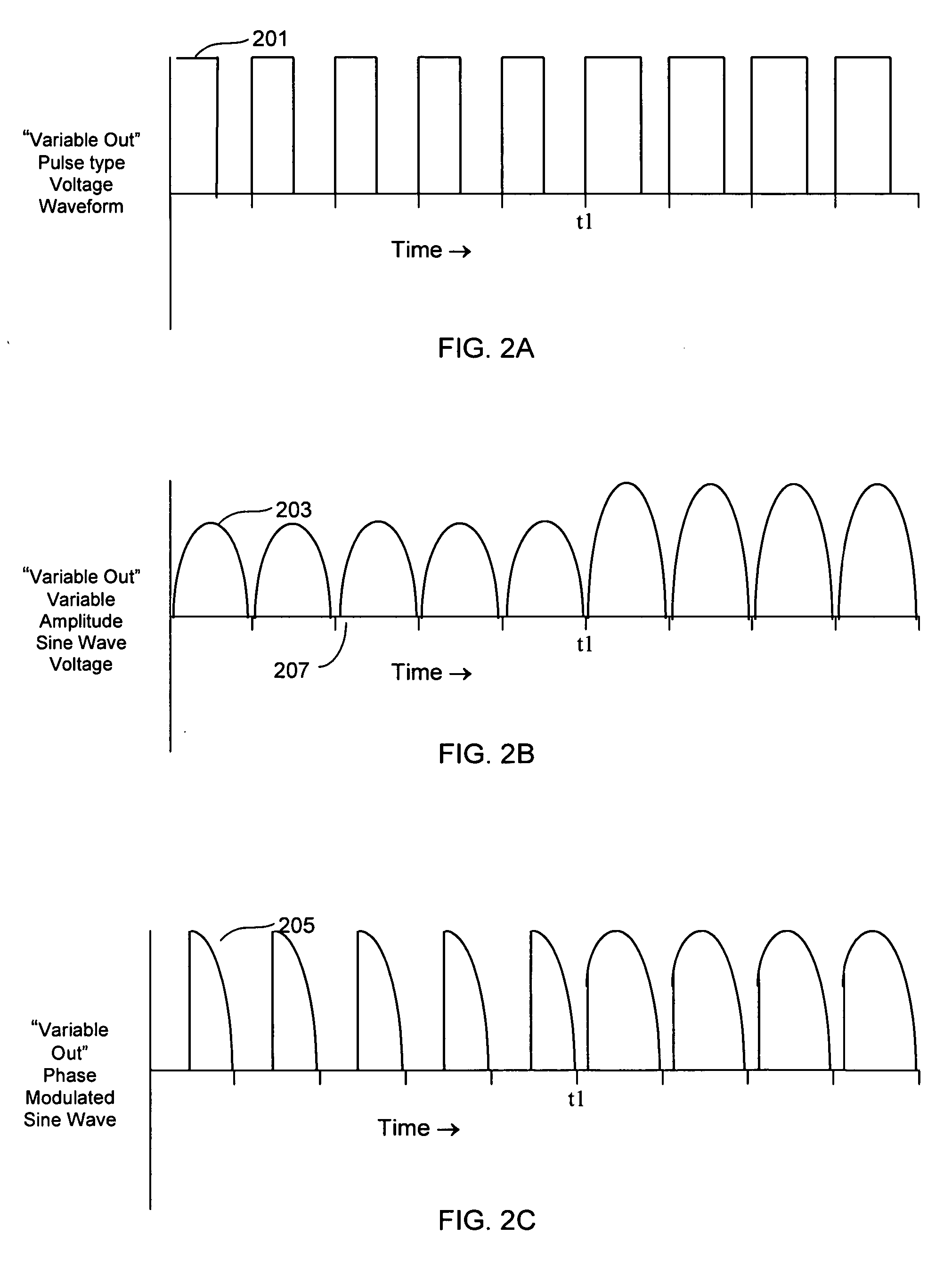
[0081] The embodiments described herein will be best understood by reference to the above-listed drawings, wherein like parts are designated by like numerals throughout. It will be readily understood that the components of the embodiments as generally described and illustrated in the figures herein could be arranged and designed in a wide variety of different configurations. Thus, the following more detailed description of various embodiments, as represented in the figures, is not intended to limit the scope of the invention, as claimed, but is merely representative of various embodiments, each of which may differ in a variety of ways. While various aspects of the embodiments are presented in the drawings, the drawings are not necessarily drawn to scale unless specifically indicated.

[0082] The phrases “connected to,”“coupled to,” and “in communication with” refer to any form of interaction directly or indirectly between two or more entities, including mechanical, electrical, magnet...


PUM


Abstract

A model train accessory controller is connectable to a DC power pack having a throttle to apply a power signal to a set of train tracks. The controller includes a switching device, which is in electrical communication with the power pack and the train tracks, to reverse a polarity of the power signal on the train tracks. The controller includes an input, and a processor in electrical communication with the switching device. The processor receives a command from the input to produce, by control of the switching device, a digital command having a series of sequential reversals in the polarity of the power signal.

Description

RELATED APPLICATION DATA [0001] This application claims priority to U.S. Provisional Patent Application Ser. No. 60 / 695,600, entitled “Model Railroad Sound and Control System,” filed Jun. 30, 2005, which is herby incorporated by reference.TECHNICAL FIELD [0002] The field of the present disclosure relates generally to model railroad systems, and more specifically, but not exclusively, to operational and simulated sound control systems for model railroads. BACKGROUND INFORMATION [0003] The model railroading industry is seeing a rapid advancement in technology. For many years the motor in all DC powered locomotives simply connected to a track pickup and the power was provided by a variable DC power pack. Making a model locomotive go fast or slow was simply a matter of applying more voltage to the track and changing direction was accomplished by changing the polarity on the track. Today, end users need more than a basic understanding of electricity and electronics. With modern command c...

Claims


Application Information

Patent Timeline
Patent Type & Authority Applications(United States)
IPC IPC(8): A63H19/24
CPCA63H19/32A63H19/24
Inventor SEVERSON, FREDERICK E.
Owner QSINDS
Why Eureka
Try Eureka