Compact solenoid

a solenoid valve, compact technology, applied in the direction of diaphragm valves, engine diaphragms, operating means/releasing devices of valves, etc., can solve the problems of reducing the internal volume of the entire system, miniaturizing individual components, and reducing the length of fluid, so as to facilitate the manufacturing of compact latch solenoid valves and simplify frame structures

Inactive Publication Date: 2007-01-04
TAKASAGO ELECTRIC
View PDF14 Cites 5 Cited by
  • Summary
  • Abstract
  • Description
  • Claims
  • Application Information

AI Technical Summary

Benefits of technology

[0021] According to the compact latching solenoid valve of the present invention, the plural bars of the frame are so disposed to have a mutual positional relationship corresponding to vertexes of a polygon, and the bars extend in parallel to the moving direction of the movable core, and in proximity to the outer circumference of the coil. Moreover, each of the bars has a generally triangular cross section. Accordingly, the width of the frame is substantially equal to the outer diameter of the coil, so that the compact latching solenoid valve is further miniaturized. Therefore, the footprint of the compact latching solenoid valves, when a plurality of them are laid out side by side, is reduced as compared with that of conventional compact latching solenoid valves.
[0022] In this compact latching solenoid valve according to the present invention, it is desired that the polygon is a rectangle, and that four bars of the frame are disposed to have a mutual positional relationship corresponding to four vertexes of the rectangle. This arrangement enables further miniaturization of a compact latching solenoid valve. In addition, this arrangement simplifies the structure of the frame, and thereby facilitates the manufacturing of the compact latching solenoid valve.

Problems solved by technology

This issue involves, in each system for mixture, reaction, and detection of fluid, a reduction of the length of fluid channel, a miniaturization of individual components, and a decrease of the entire internal volume of the system.
Especially when more than one solenoid valves are arranged side by side, the miniaturization of each solenoid valve will directly conduce to a reduction of the length of fluid channel, and therefore, the miniaturization of the solenoid valve can be the most important issue.

Method used


Image

  • Compact solenoid
  • Compact solenoid
  • Compact solenoid

Examples


Embodiment Construction

[0040] Preferred embodiments of the present invention are now described below with reference to the accompanying drawings. However, the invention is not limited to the embodiments disclosed herein. All modifications with in the appended claims and equivalents relative thereto are intended to be encompassed in the scope of the claims.

[0041] Firstly, a compact solenoid 100 embodying the present invention is described.

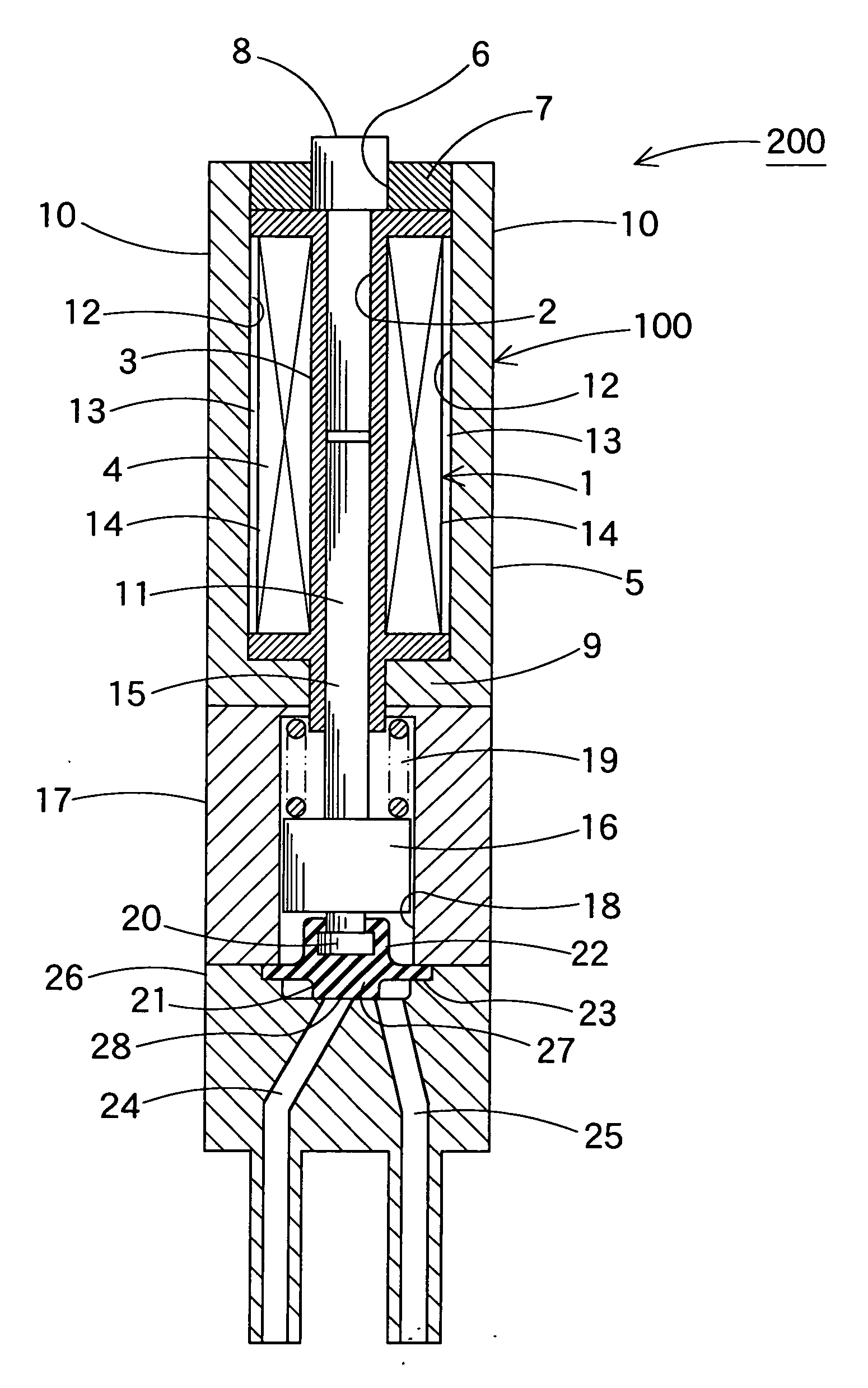
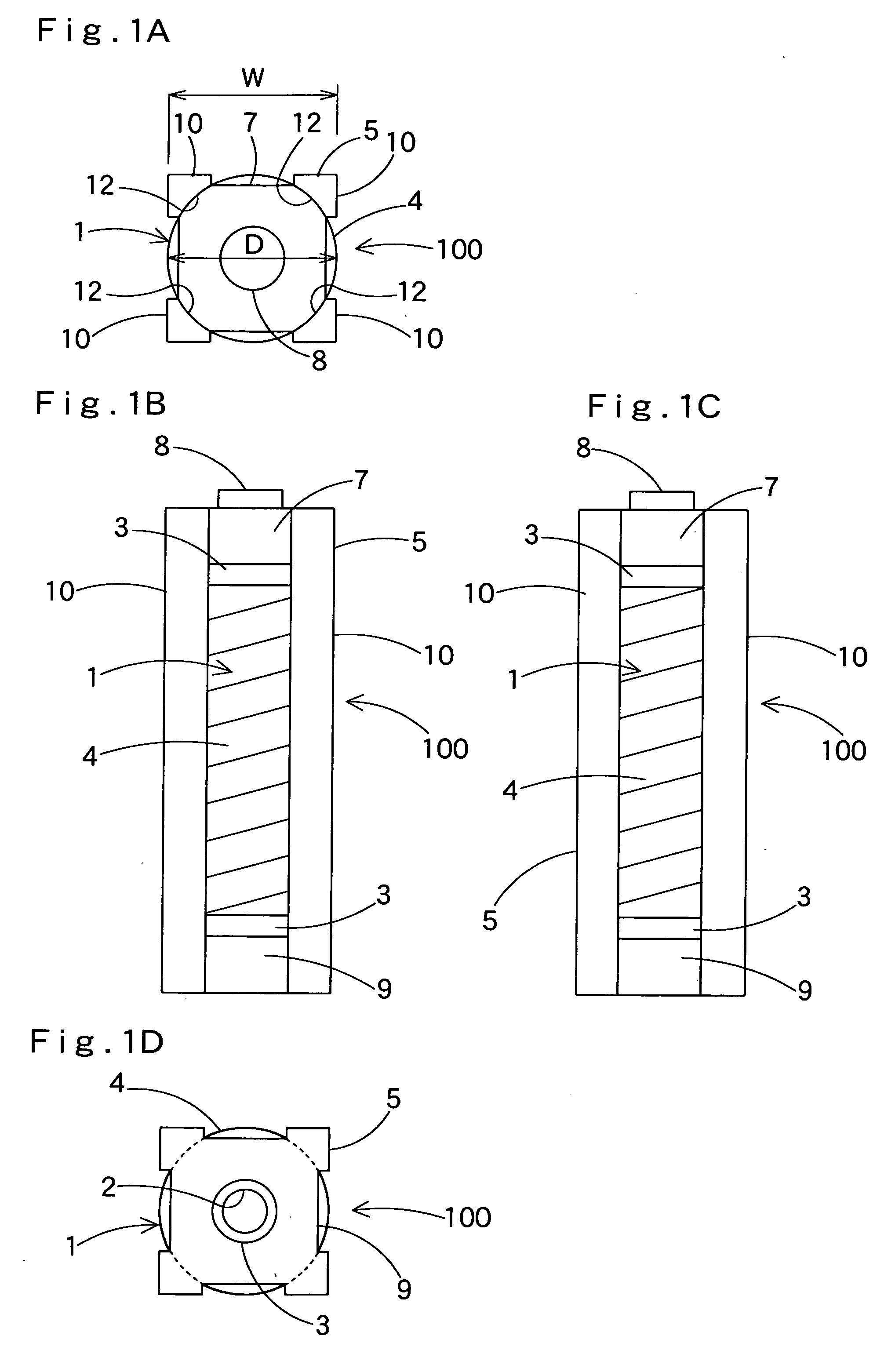
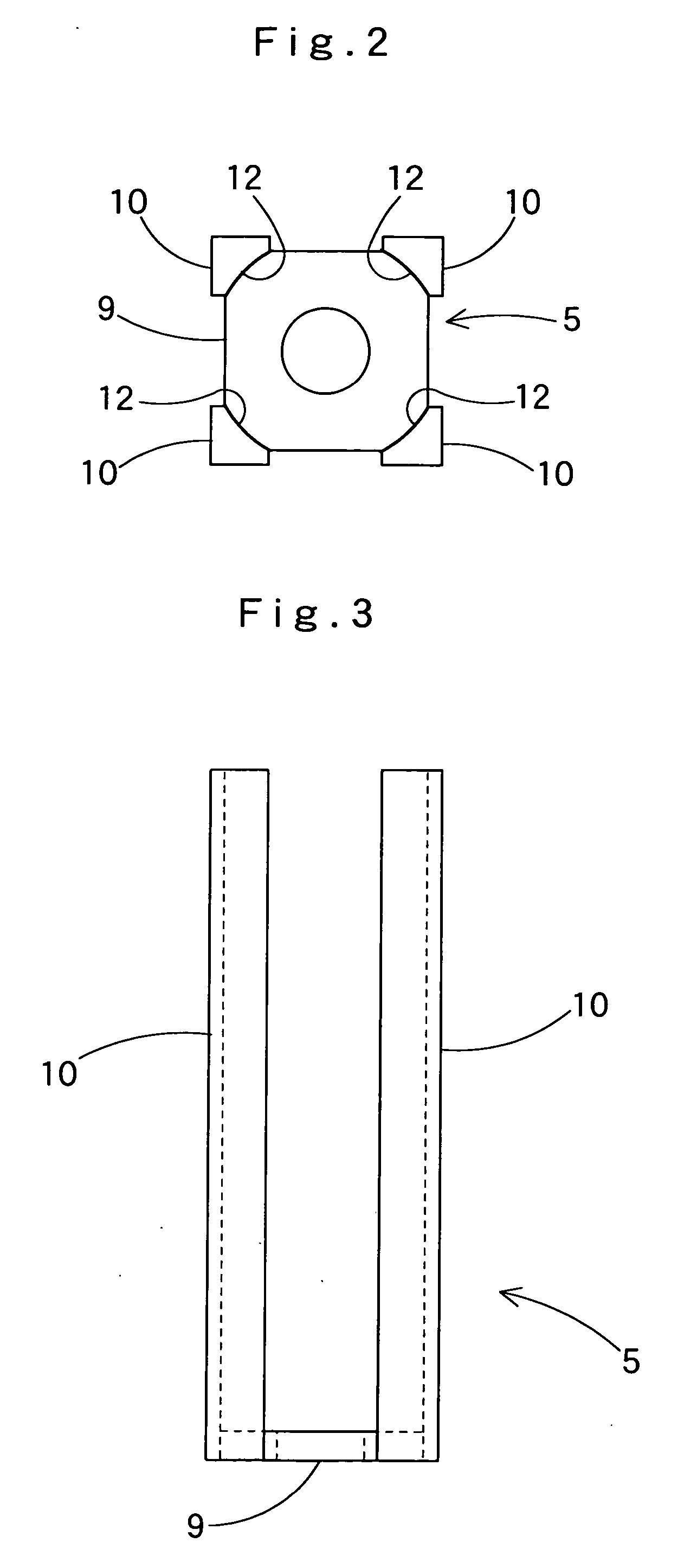
[0042] As shown in FIGS. 1A, 1B, 1C, 1D, 2, 3 and 4, the compact solenoid 100 includes a cylindrical hollow coil 1. As shown in FIGS. 7 and 8, the coil 1 is formed by winding a winding wire 4 around a bobbin 3 having an inner bore 2. Outside of the coil 1 is a frame 5 made from a magnetic material, which frame forms a magnetic circuit. The frame 5can be paraphrased a housing 5. In an end face of the coil 1 is arranged a plate-like end cap 7 having a circular hole 6. A stationary core 8 is inserted through the hole 6 of the end cap 7 and into a part of the inner bore 2, ...


PUM


Abstract

The compact solenoid of the present invention conduces to further miniaturization of a compact solenoid. The compact solenoid includes a coil and a frame located outside the coil for constituting a magnetic circuit. The frame includes four bars extending in parallel to the axial direction of the coil and located proximate to the outer circumferential face of the coil. Each of the bars has a generally triangular cross section. The four bars are disposed to have a mutual positional relationship corresponding to vertexes of a square.

Description

[0001] The present application claims priority from Japanese Patent Application No. 2005-190191 of Asai et al., filed on Jun. 29, 2005, the disclosure of which is hereby incorporated into the present application by reference. BACKGROUND OF THE INVENTION [0002] 1. Field of the Invention [0003] The present invention relates to a compact solenoid, a compact solenoid valve and, a compact latching solenoid valve. [0004] 2. Description of the Related Art [0005] In such instruments as an apparatus for chemical examination, environmental analysis, or biotechnological research, it is an important issue to improve accuracy and to minimize a sample or reagent. This issue involves, in each system for mixture, reaction, and detection of fluid, a reduction of the length of fluid channel, a miniaturization of individual components, and a decrease of the entire internal volume of the system. Accordingly, it is also required to miniaturize a solenoid valve, which is broadly used in the fluid control...

Claims


Application Information

Patent Timeline
Patent Type & Authority Applications(United States)
IPC IPC(8): F16K31/08
CPCF16K31/06F16K7/14
Inventor ASAI, NAOYASUGIURA, HIROYUKI
Owner TAKASAGO ELECTRIC
Why Eureka
Try Eureka