Bi-directional single-phase fan and motor thereof

a single-phase fan and motor technology, applied in the direction of motor/generator/converter stopper, dc motor rotation control, dynamo-electric converter control, etc., can solve the problem of reducing the operation efficiency, dust accumulation on the air filter after, and the phase fan in the prior art can only provide airflow in one direction, so as to improve the use efficiency and correct the magnetic pole of the rotor. , the effect of improving the airflow efficiency

Inactive Publication Date: 2007-01-04
DELTA ELECTRONICS INC
View PDF6 Cites 11 Cited by
  • Summary
  • Abstract
  • Description
  • Claims
  • Application Information

AI Technical Summary

Benefits of technology

[0013] In the above-mentioned fan and motor, a delay unit can be added to connect with the control circuit, preventing the fan from damaging the control circuit caused by the short current formed while the fan changes its rotating direction.
[0014] As mentioned above, a bi-directional single-phase fan and a motor thereof according to the present invention can provide either forward or backward airflow in accordance with needs. The first inductive element and the second inductive element can be switched on and off according to the rotating direction. Therefore, they can correctly detect the magnetism of the magnetic poles of the rotor. Comparing with the prior art, the present invention can maintain good airflow efficiency in either rotating direction of the rotor. Moreover, the design of the delay unit can prevent a short current from happening when the fan changes its rotating direction, ensuring safer usage of the fan. Besides, the present invention can clean the dusts on the blades or air filter by changing the airflow direction of the fan.

Problems solved by technology

Therefore, the single-phase fan in the prior art can only provide airflow in single direction.
Moreover, if the conventional single-phase fan is installed with air filters, the dust is accumulated on the air filters after the fan operating for a period of time.
This will reduce the operation efficiency, increase the noise during operation, and shorten the lifetime of the fan.

Method used


Image

  • Bi-directional single-phase fan and motor thereof
  • Bi-directional single-phase fan and motor thereof
  • Bi-directional single-phase fan and motor thereof

Examples


Embodiment Construction

[0019] The present invention will be apparent from the following detailed description, which proceeds with reference to the accompanying drawings, wherein the same references relate to the same elements.

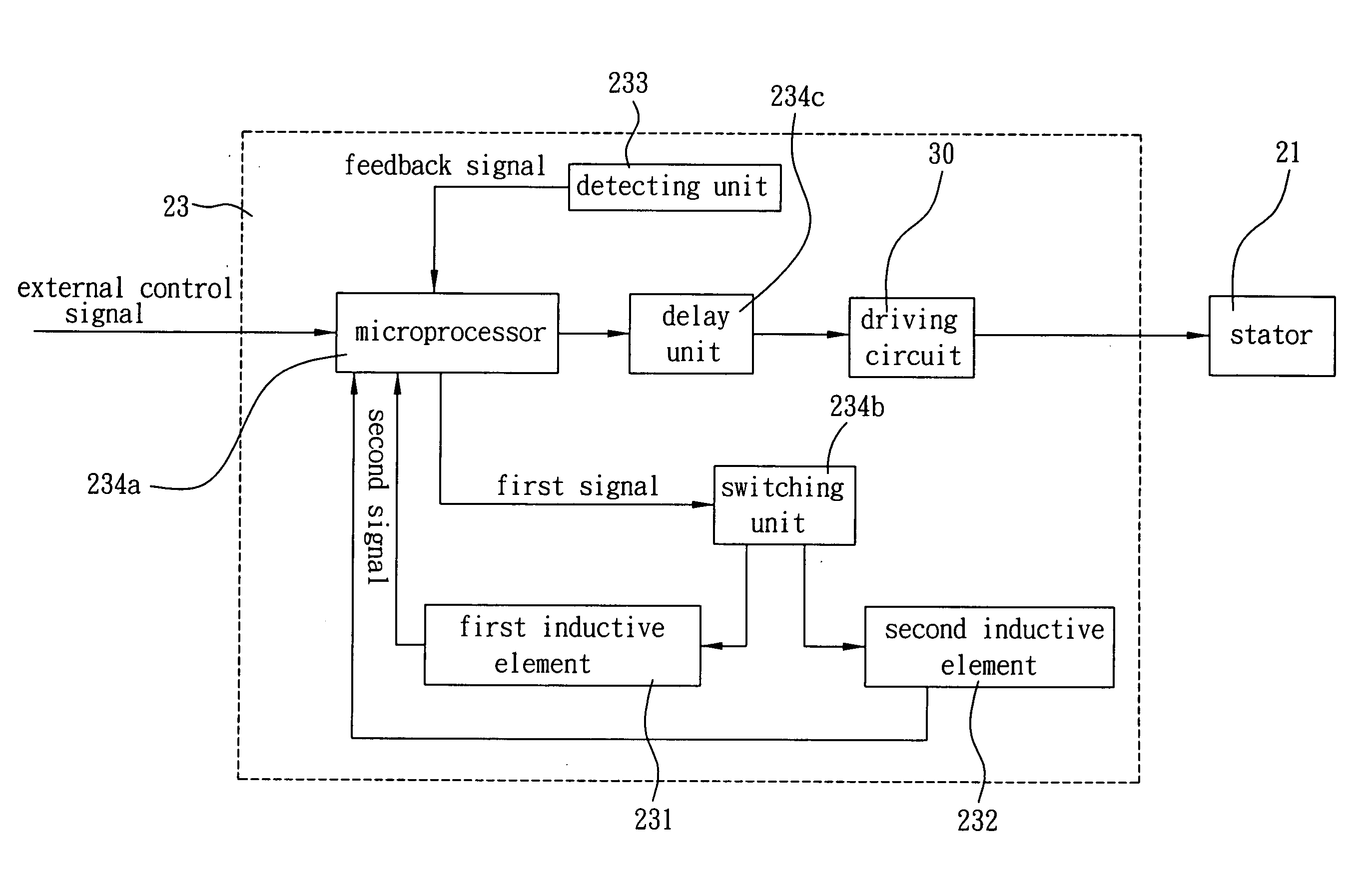
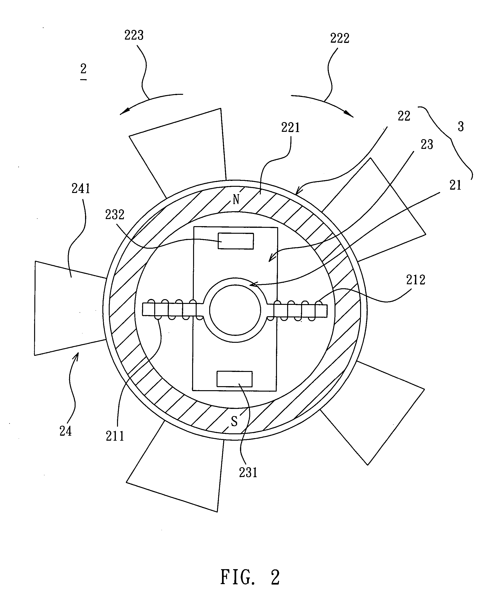
[0020] As shown in FIG. 2, a bi-directional single-phase fan 2 according to the present invention includes a stator 21, a rotor 22, a control circuit 23 and an impeller 24. The stator 21, the rotor 22 and the control circuit 23 constitute a single-phase motor 3.

[0021] The stator 21 has a first coil 211 and a second coil 212 as the magnetic poles of the stator 21.

[0022] The rotor 22 has a permanent magnet 221 coupled to the stator 21. Due to the variation of the magnetic forces among the first coil 211, the second coil 212 and the permanent magnet 221, the rotor 22 rotates along a first direction 222 or a second direction 223 with respect to the stator 21.

[0023] The control circuit 23 is disposed in the stator 21 and has a first inductive element 231 and a second inductive element...


PUM


Abstract

A bi-directional single-phase motor includes a stator, a rotor and a control circuit. The rotor is coupled to the stator and rotates along a first direction or a second direction. The control circuit is disposed in the stator and has a first inductive element and a second inductive element. When the first inductive element is on and the second inductive element is off, the rotor rotates along the first direction. When the first inductive element is off and the second inductive element is on, the rotor rotates along the second direction.

Description

BACKGROUND OF THE INVENTION [0001] 1. Field of Invention [0002] The present invention relates to a fan and a motor thereof, and more particularly, to a bi-directional single-phase fan and a motor thereof. [0003] 2. Related Art [0004] As shown in FIG. 1, a conventional single-phase fan 1 has a stator 11, a rotor 12 coupled to the stator 11, and an impeller 13 disposed on the rotor 12. The stator 11 has a first coil 111 and a second coil 112. The rotor 12 has a permanent magnet 121. The impeller 13 has a plurality of blades 131. [0005] The stator 11 further has a Hall element 113 electrically connected to the first coil 111 and the second coil 112 for detecting the pole position of the permanent magnet 121 of the rotor 12. [0006] Moreover, to prevent the single-phase fan 1 from hurting the user during its operation, the inlet and outlet sides of the single-phase fan 1 are respectively added with an air filter (not shown). [0007] The single-phase fan 1 is currently, designed to provide...

Claims


Application Information

Patent Timeline
Patent Type & Authority Applications(United States)
IPC IPC(8): H02P7/06
CPCH02P7/0038H02P7/03
Inventor WEI, CHIA-PINCHEN, YI-LUN
Owner DELTA ELECTRONICS INC
Why Eureka
Try Eureka