Internal chip antenna

a chip antenna and antenna technology, applied in the direction of resonant antennas, substantially flat resonant elements, elongated active element feed, etc., can solve the problems of lacking applicability as an internal antenna, conventional internal antennas cannot process low band frequencies of terrestrial dmb, etc., and achieve the effect of easy control of impedan

Inactive Publication Date: 2007-01-04
SAMSUNG ELECTRO MECHANICS CO LTD
View PDF0 Cites 26 Cited by
  • Summary
  • Abstract
  • Description
  • Claims
  • Application Information

AI Technical Summary

Benefits of technology

[0011] The present invention has been made to solve the foregoing problems of the prior art and therefore an object according to certain embodiments of

Problems solved by technology

Therefore, disadvantageously, the conventional internal antenna cannot process low band frequencies of e.g., terrestrial DMB.
As a result, the antenna manu

Method used


Image

  • Internal chip antenna
  • Internal chip antenna
  • Internal chip antenna

Examples


Embodiment Construction

[0026] Preferred embodiments of the present invention will now be described in detail with reference to the accompanying drawings, in which the same reference numerals are used throughout the different drawings to designate the same or similar components. In the following description, well-known functions and constructions are not described in detail since they would obscure the intention in unnecessary detail.

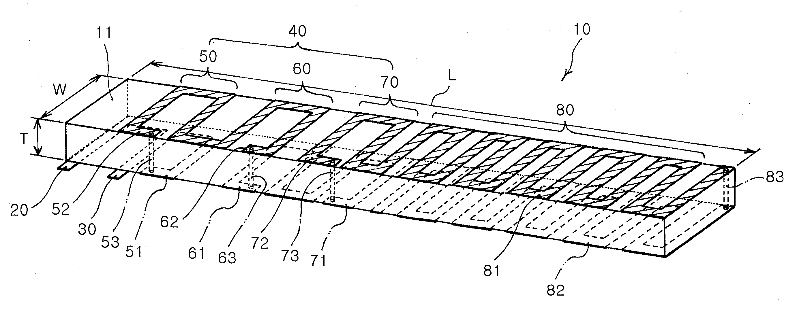
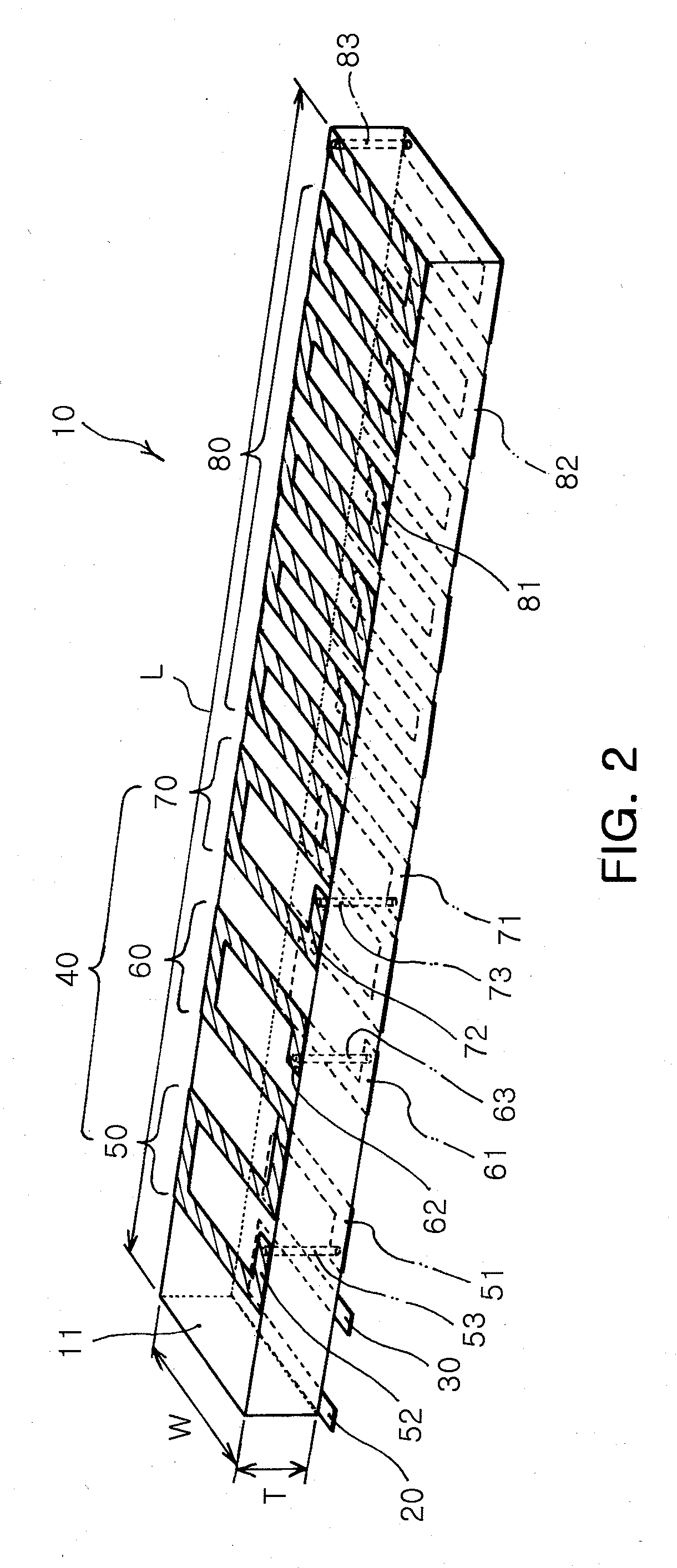
[0027]FIG. 2 is a configuration view illustrating an internal or built-in chip antenna according to an embodiment of the invention.

[0028] Referring to FIG. 2, the chip antenna 10 according to the embodiment of the invention includes a substrate 11, a ground part 20, a feeding part 30, a spiral first radiator 40, and a meander-shaped second radiator 80. To ensure the chip antenna 10 to be used in a low frequency band of e.g., terrestrial DMB as an ultra-small structure, the substrate 11 is made of a magnetic dielectric material. Also, to achieve an impedance match easily, the...


PUM


Abstract

The invention provides a chip antenna installed inside a mobile telecommunication terminal, which can process a low band signal. In the chip antenna, a substrate is prepared. A first radiator is formed in a spiral shape inside or on the substrate, and includes at least one spiral radiating part. The first radiator controls inductance of the antenna. Also, a second radiator is connected to the first radiator, and includes an upper meander radiating part disposed in a length direction of the substrate and a lower meander radiating part overlapping and opposing the upper meander in a lower part of the upper meander part. The second radiator controls capacitance of the antenna. In addition, a feeding part is connected to the first radiator, and receives a high frequency current of a given band.

Description

CLAIM OF PRIORITY [0001] This application claims the benefit of Korean Patent Application No. 2005-58272 filled on Jun. 30, 2005 in the Korean Intellectual Property Office, the disclosure of which is incorporated herein by reference. BACKGROUND OF THE INVENTION [0002] 1. Field of the Invention [0003] The present invention relates to an antenna installed inside a mobile telecommunication terminal, for transmitting and receiving a wireless signal. More particularly, the present invention relates to a chip antenna installed inside a mobile telecommunication terminal, capable of processing a low band signal. [0004] 2. Description of the Related Art [0005] Recently, a rising demand for wireless devices installed inside mobile telecommunication terminals has led to diversity in frequency bands used in an antenna of the terminals. Specifically, frequency bands currently used in the mobile telecommunication terminals include 800 MHz to 2 GHz (for mobile phones), 2.4 GHz to 5 GHz (for wirele...

Claims


Application Information

Patent Timeline
IPC IPC(8): H01Q1/36
CPCH01Q1/36H01Q1/243H01Q1/2283H01Q9/42H01Q9/0407
Inventor BAE, SEOKYASUHIKO, MANO
Owner SAMSUNG ELECTRO MECHANICS CO LTD
Why Eureka
Try Eureka