Transflective liquid crystal display device

Inactive Publication Date: 2007-01-04
NEC LCD TECH CORP
View PDF7 Cites 89 Cited by
  • Summary
  • Abstract
  • Description
  • Claims
  • Application Information

AI Technical Summary

Benefits of technology

[0024] It is an object of the present invention to provide a transflective LCD device which is capable of solving the image-inversion problem encountered in the conventional transflective LCD device due to, for ex

Problems solved by technology

If the IPS mode or FFS mode using a lateral electric field is to be employed in the transflective LCD device as described above, there arises an image-inversion problem in the LCD device, as described in the patent publication as mentioned above.
The image-inversion problem is a general problem common to the lateral-electric-field modes (IPS mode, FFS mode) and other LCD modes.
That is, the lateral-electric-field-mode LCD device cannot repr

Method used


Image

  • Transflective liquid crystal display device
  • Transflective liquid crystal display device
  • Transflective liquid crystal display device

Examples


first embodiment

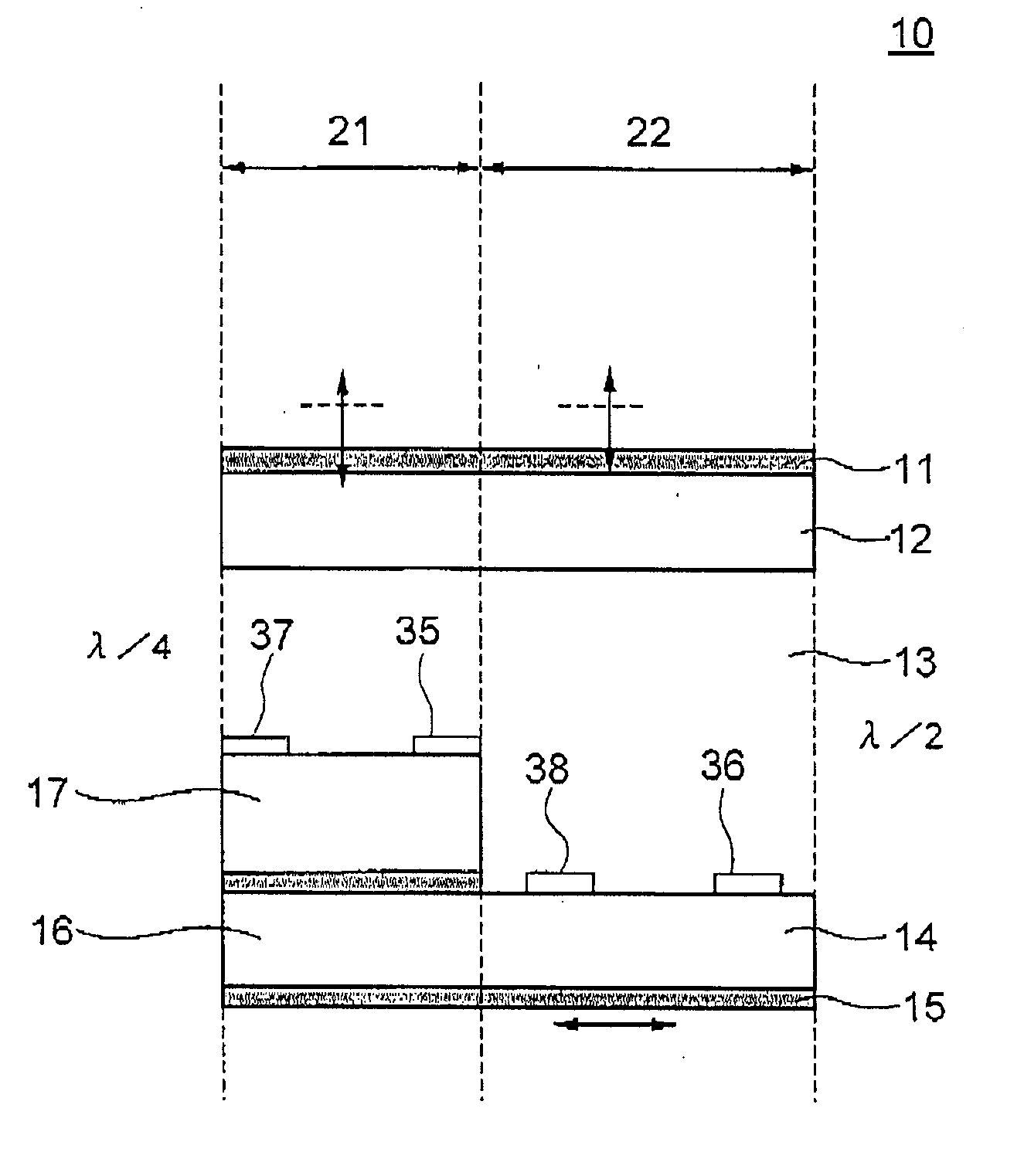
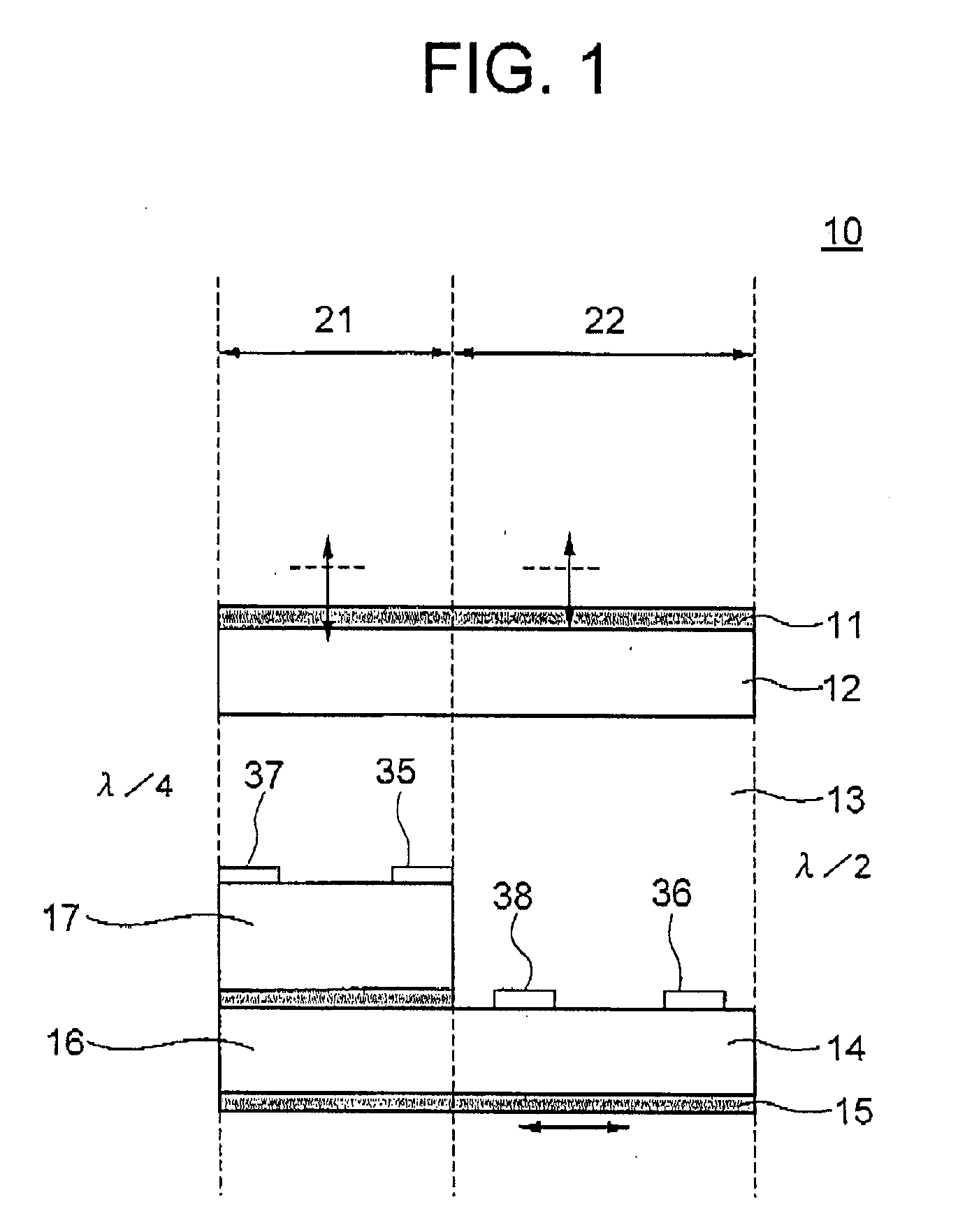
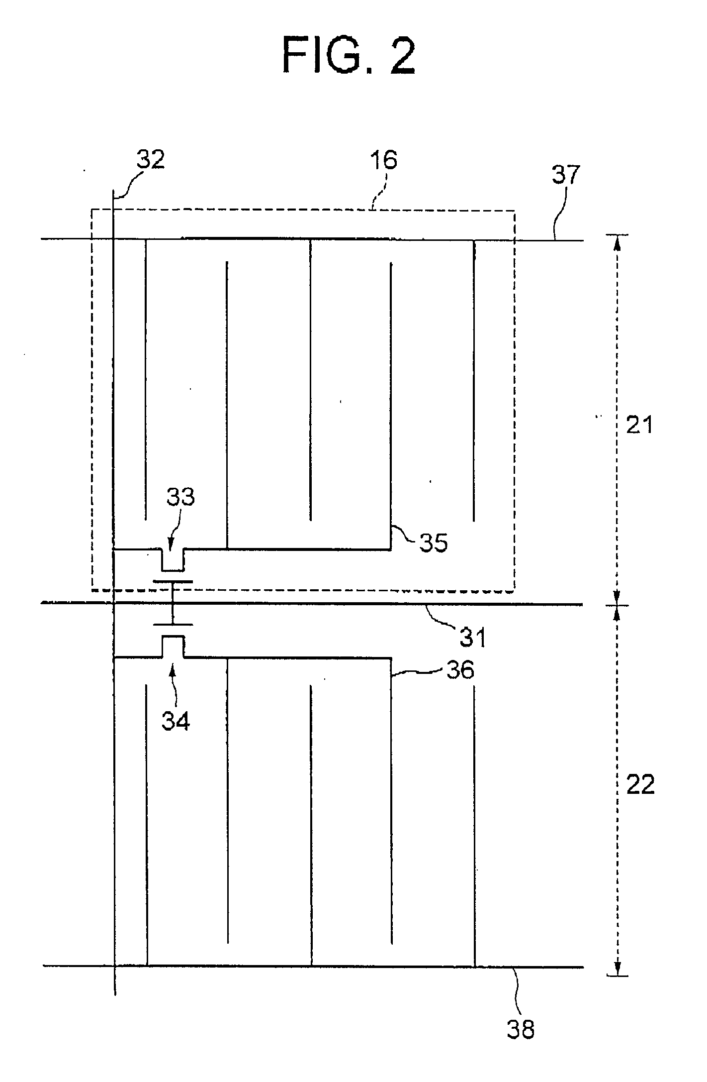
[0071]FIG. 1 is a sectional view schematically showing a pixel in a transflective LCD device according to the present invention. FIG. 2 is a schematic top plan view of the TFT substrate in the pixel shown in FIG. 1. The LCD device, generally designated by numeral 10, includes a first polarizing film 11, counter substrate (first substrate) 12, a LC layer 13, a TFT substrate (second substrate) 14, and a second polarizing film 15, which are arranged in this order from the front side toward the rear side of the LCD device 10. The first polarizing film 11 has a optical transmission axis at 90 degrees, and thus an absorption axis at zero degree, whereas the second polarizing film 15 has an optical transmission axis at zero degree, and thus an absorption axis of 90 degrees. The LC layer 13 includes LC molecules having a longer axis at 90 degrees upon absence of the applied voltage, in this example.

[0072] Each pixel of the LCD device 10 includes a reflective region 21 and a transmissive reg...

second embodiment

[0120] The seventh combination is applied to the LCD device 10c of the second embodiment, which exhibits the polarized state shown in FIG. 21. The function of this LCD device will be described hereinafter during display of a dark state and display of a bright state.

Display of a Dark State

[0121] For display of a dark state in this embodiment, the driving signals shown in FIGS. 3A and 3B are used so as to rotate the longer axis of the LC molecules in the LC layer 13 in the reflective region 21 by 45 degrees, and maintains the longer axis of the LC molecules in the transmissive region 22 at 90 degrees. In FIG. 21, dotted line represents the direction of the polarized light, and the solid arrows represent the optical absorption axis.

[0122] In the transmissive region 22, a 135-degree linearly-polarized light passed by the second polarizing film 15 having an optical transmission axis at 135 degrees (and thus an absorption axis at 45 degrees) is rotated by an angle equal to double the d...

fourth embodiment

[0131] In the above embodiments, IPS-mode LCD device is exemplified as the LCD device of the embodiments. The display mode of the LCD device of the first invention, for example, may be a fringe-field-switching(FFS)-mode instead. FIG. 32 shows a sectional view of the FFS-mode LCD device according to the present invention, The LCD device, generally designated by numeral 10d, includes a reflective region 21 and a transmissive region 22. On the TFT substrate 14a, a reflection film 16 and an embedding insulation film are formed in the reflective region 21. The reflection film 16 reflects the light incident from the first polarizing film 11. The reflection film 16 has an uneven surface in general for improving the light dispersion effect; however, a dispersion film may be additionally provided in the counter substrate 12 instead of providing the uneven surface to the reflection film 16. In a further alternative, a dispersion adhesive layer wherein light dispersion beads are dispersed may ...


PUM


Abstract

An IPS-mode transflective LCD device includes an array of pixels each including a reflective region and a transmissive region juxtaposed. The reflective region operates in a normally-white mode, and the transmissive region operates in a normally-black mode. A common data signal is supplied to the reflective region and transmissive region, whereas the common electrode signal in the transmissive region is an inverted signal of the common electrode signal in the reflective region, to thereby obtain similar gray-scale levels.

Description

BACKGROUND OF THE INVENTION [0001] (a) Field of the Invention [0002] The present invention relates to a transflective liquid crystal display (LCD) device including a transmissive area and a reflective area in each pixel of the LCD device. [0003] (b) Description of the Related Art [0004] LCD devices are generally categorized in two types: a transmissive LCD device having therein a backlight unit as a light source; and a reflective LCD device having therein a reflection film which reflects external light incident onto the LCD device and thus functions as a light source. The reflective LCD device has the advantages of lower power dissipation, smaller thickness and lighter weight compared to the transmissive LCD device, due to absence of a backlight source in the reflective LCD device. On the other hand, the transmissive LCD device is superior to the reflective LCD device in that the transmissive LCD device can be well observed in a dark environment. [0005] There is another type of the ...

Claims


Application Information

Patent Timeline
IPC IPC(8): G02F1/1335
CPCG02F1/133555G02F1/134363G09G3/3655G09G3/3659G09G2300/0408G09G2300/0456G09G2320/028G02F1/1335
Inventor SAKAMOTO, MICHIAKIMATSUSHIMA, JINNAGAI, HIROSHIMORI, KENICHIIKENO, HIDENORIKUDO, YASUKISUMIYOSHI, KEN
Owner NEC LCD TECH CORP
Why Eureka
Try Eureka