
Interpolation of images

a technology of interpolation and images, applied in the field of interpolation of images, can solve the problem of requiring a relativly complex algorithm, and achieve the effect of high-performance algorithm

Inactive Publication Date: 2007-01-04
KONINKLIJKE PHILIPS ELECTRONICS NV
View PDF5 Cites 6 Cited by
  • Summary
  • Abstract
  • Description
  • Claims
  • Application Information

AI Technical Summary

Benefits of technology

The invention provides a method for performing a high-performance interpolation on a two-dimensional image using a warped distance interpolator. The method determines the direction of change of values in the image using a local gradient, and selects interpolator input values in the direction of the gradient to perform the interpolation. The warping factor is determined for the interpolator input values, which are interpolated from neighboring input samples. The invention also provides a system for scaling the image and a method for determining the local gradient in the input map. The technical effects of the invention include improved performance and efficiency in image interpolation.

Problems solved by technology

It is a disadvantage that a relatively complex algorithm is required.

Method used


Image

  • Interpolation of images
  • Interpolation of images
  • Interpolation of images

Examples


first embodiment

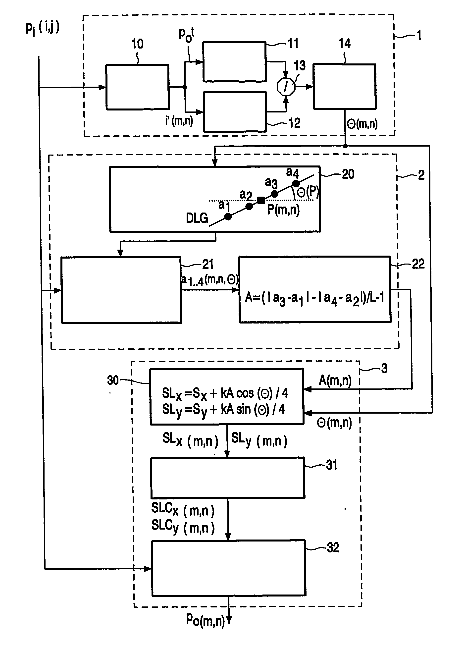
[0044] Two possible embodiments are elucidated for determining the local gradient θ. In the first embodiment, the input image II is first interpolated with a known algorithm, for example with a bilinear filter, to obtain roughly interpolated output samples. The local gradient θ is determined in the output domain from these output samples. For example, by using a Sobel filter. Possible masks of Sobel filters to obtain a value of the directional derivative along x and y directions are: Sobelx=(1 / 40-1 / 41 / 20-1 / 21 / 40-1 / 4)Sobely=(-1 / 4-1 / 2-1 / 40001 / 41 / 21 / 4)

[0045] The direction of the gradient θ at the position xi,yj is then estimated as follows:

θ(x1,yj)=arctan((f1*Sobely)|(x1,yj) / (f1*Sobelx)|(x1,yj))  (7)

wherein f1 is the result of the rough interpolation of the input image II, and θ is an angle which varies between −π / 2 and π / 2.

[0046] The gradient evaluation has been performed by using Sobel's method in the output domain. A pre-processing, for example a simple bilinear interpolator, i...

second embodiment

[0061]FIG. 5 shows a flowchart of part of another embodiment of the one step Warped Distance concept in accordance with the invention. FIG. 5 shows the steps required in the step 1 which determines the direction of the local gradient θ(m,n) in accordance with the second embodiment discussed before. Now, step 1 comprises the steps 15 and 16 instead of the steps 10 to 14 shown in FIG. 4. In step 15, the direction of the local gradients θ(i,j) is determined in the input image II for the input samples Pi. The step 16 maps these local gradients θ(i,j) from the input domain to the output domain to obtain local gradients θ(m,n) for the output pixels Po. The other steps of the WaDi processing of this embodiment in accordance with the invention are equal to the steps shown in FIG. 4.

[0062]FIG. 6 shows a block diagram of a display apparatus comprising the Warped Distance interpolator in accordance with the invention. An input video processor IVP processes input video IV to obtain the input im...


PUM


Abstract

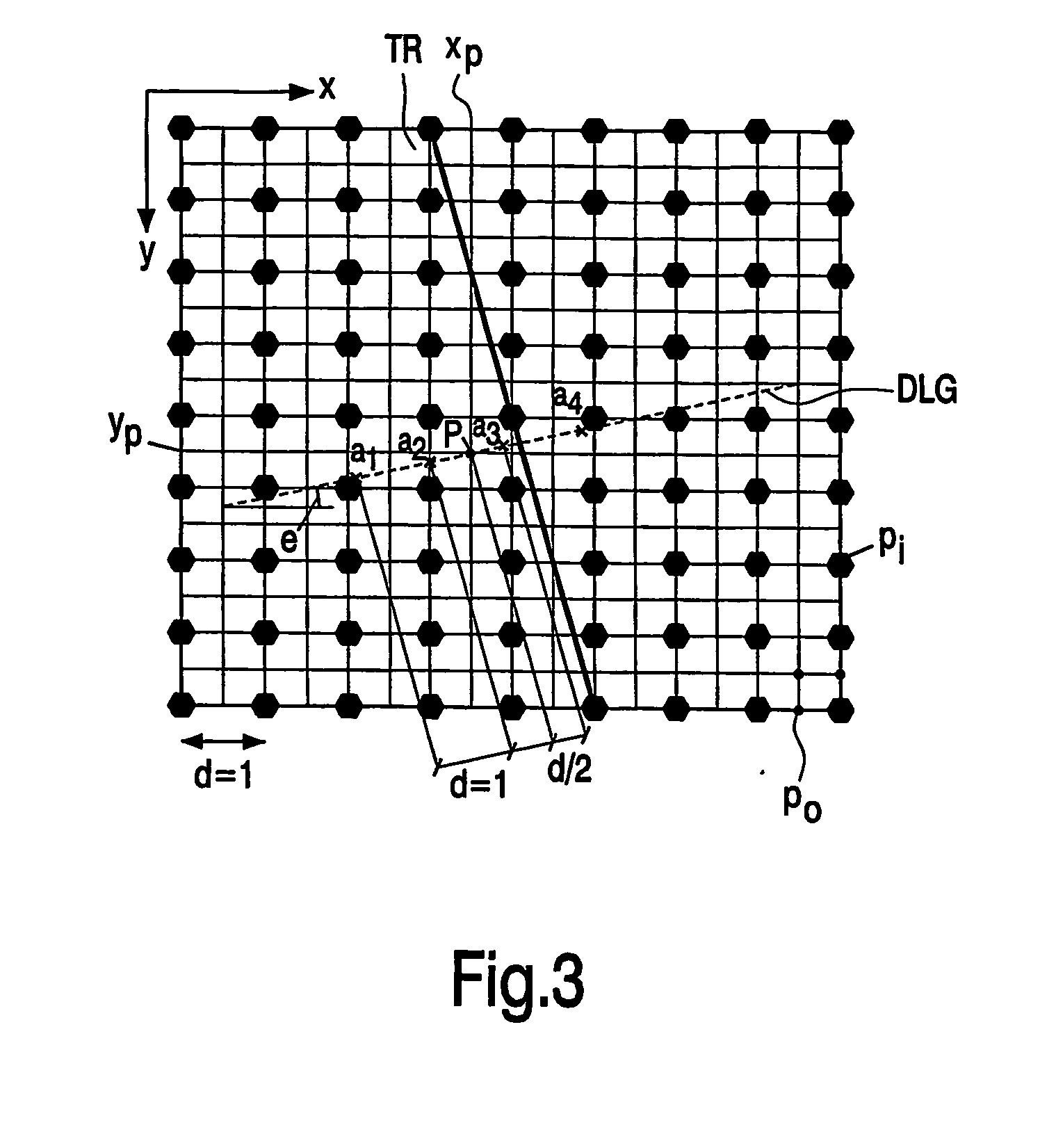
In a method of interpolating sample values (f) of samples (Pi, Pot) of an image, a direction of a local gradient (8) of the sample values (f) for a particular one of the samples (Pi, Pot) is determined (1) from sample values (f) neighboring the particular one of the samples (Pi, Pot). The positions of interpolator input values (ai) are selected (20) in the direction of the local gradient (8) of the particular one of the samples (Pi, Pot). The interpolator input values (ai) for the particular one of the samples (Pi, Pot) are interpolated (21) from pixel values (f) neighboring the interpolator input values (ai). And, a warping factor (A) for a warped distance interpolating (3) is determined (22) using the interpolator input values (ai).

Description

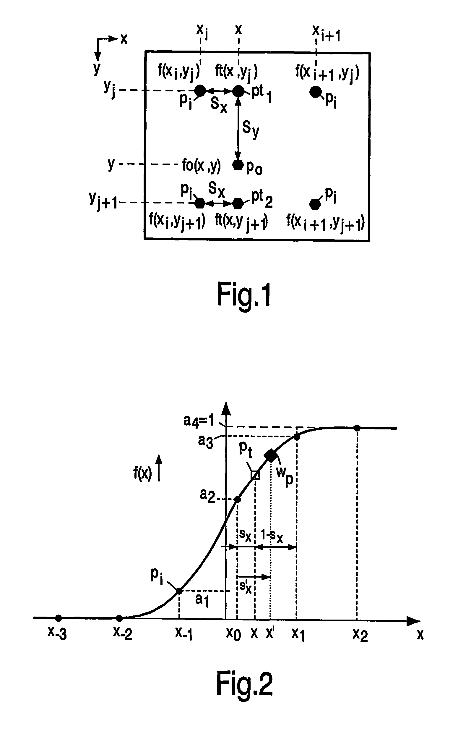
FIELD OF THE INVENTION [0001] The invention relates to a method of interpolating pixel values of pixels of an image. The invention further relates to a warped distance interpolator, and to a display apparatus comprising such a warped distance interpolator. BACKGROUND OF THE INVENTION [0002] The warped distance concept (WaDi) is known from the publication “Warped distance for space-variant linear image interpolation”, IEEE Transactions on Image processing, vol. 8 no. 5, May 1999 by G. Ramponi. The Warped Distance concept for linear interpolators adapts a linear interpolator to the local pixel configuration of natural (non graphic) images. Particularly, the aim was to prevent edges from being blurred by the interpolation process. [0003] The WaDi concept performs a one dimensional interpolation. In the horizontal direction, an interpolated sample could be a linear combination of the two neighboring horizontal samples sandwiching the sample to be interpolated. The linear combination dep...

Claims


Application Information

Patent Timeline
Patent Type & Authority Applications(United States)
IPC IPC(8): G06K9/32G06T3/40
CPCG06T3/4007G06T3/40
Inventor FERRETTI, GIULIOCARRAI, PAOLAZOTTA, FRANCESCORAMPONI, GIOVANNI
Owner KONINKLIJKE PHILIPS ELECTRONICS NV
Learn More