Temporary vascular filter

a technology of vascular filter and filter body, which is applied in the field of temporary vascular filter, can solve the problems of inaccurate deployment, cumbersome use of filter, and inability to achieve exceptional effectiveness of filter in actual use, and achieve the effect of effective forming a particulate seal

Inactive Publication Date: 2007-01-04
EV3
View PDF63 Cites 52 Cited by
  • Summary
  • Abstract
  • Description
  • Claims
  • Application Information

AI Technical Summary

Benefits of technology

[0007] Further refinements of this method are envisioned. For example, in one embodiment, the filter has a narrow proximal end which is smaller than the lumen of the catheter. In drawing the proximal length of the filter within the catheter, this narrow proximal end may be introduced into the distal end of the catheter's lumen. The filter may then be retracted until the internal surface of the catheter engages the body of the filter distally of the opening to effectively create a particulate seal therebetween.

Problems solved by technology

However, most such filters generally have not proven to be exceptionally effective in actual use.
These filters tend to be cumbersome to use and accurate deployment is problematic because if they are not properly seated in the vessel they can drift to a more distal site where they are likely to do more harm than good.
In addition, these filters are generally capable of only trapping relatively large thrombi and are not effective for removing smaller embolic particles from the blood stream.
The problems with most temporary filters, which are intended to be used only during a particular procedure then retracted with the thrombi trapped therein, are more pronounced.
Even if the trap does effectively capture the dislodged material, it has proven to be relatively difficult or complex to retract the trap back into the catheter through which it was delivered without simply dumping the trapped thrombi back into the blood stream, defeating the purpose of the temporary filter device.

Method used


Image

  • Temporary vascular filter
  • Temporary vascular filter
  • Temporary vascular filter

Examples


Embodiment Construction

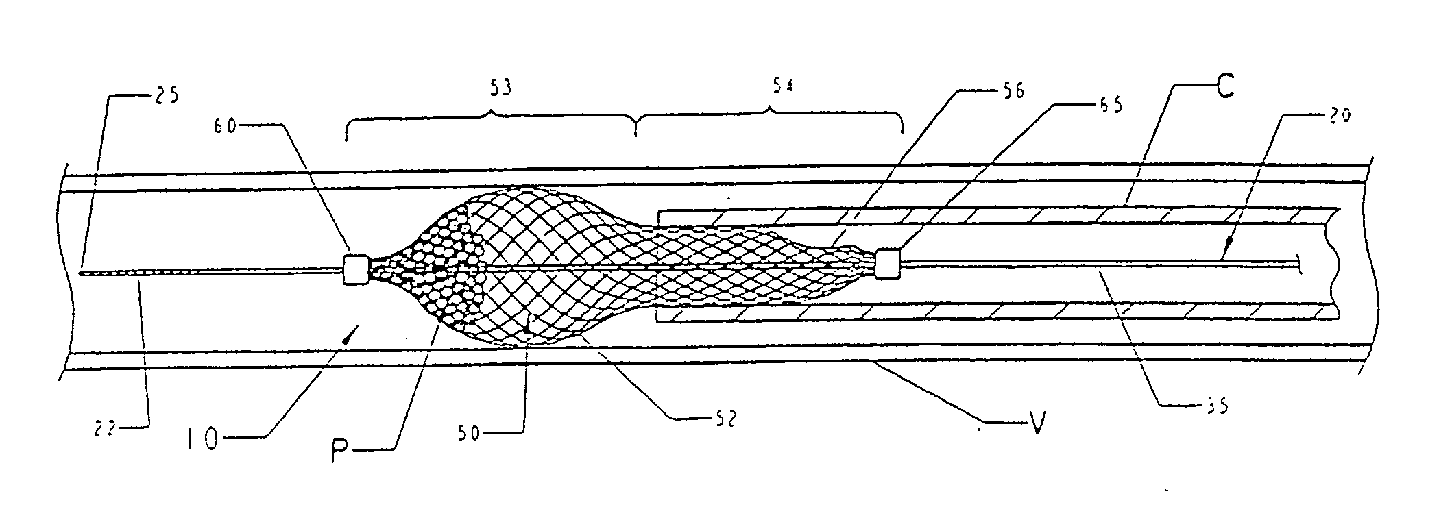
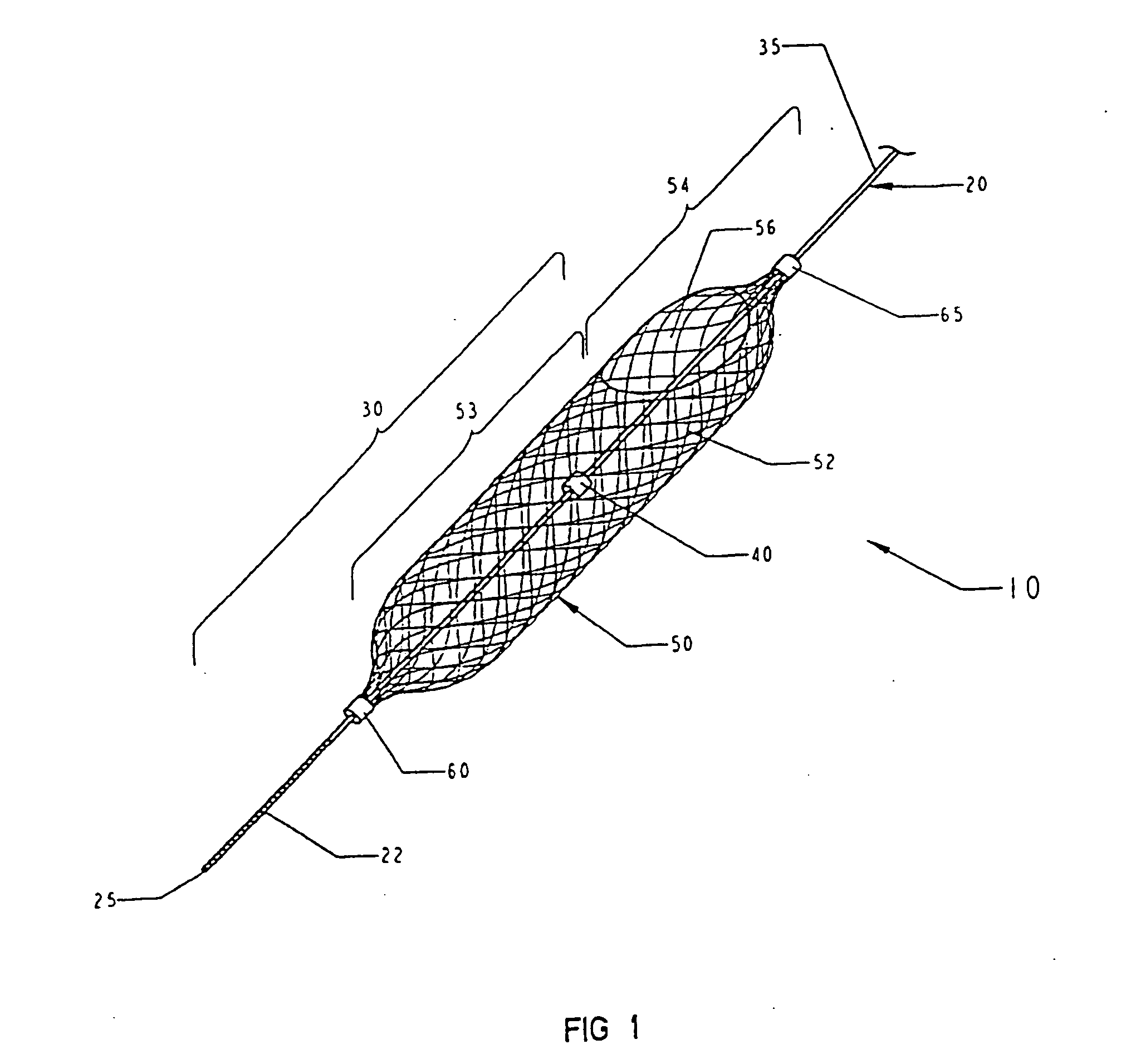
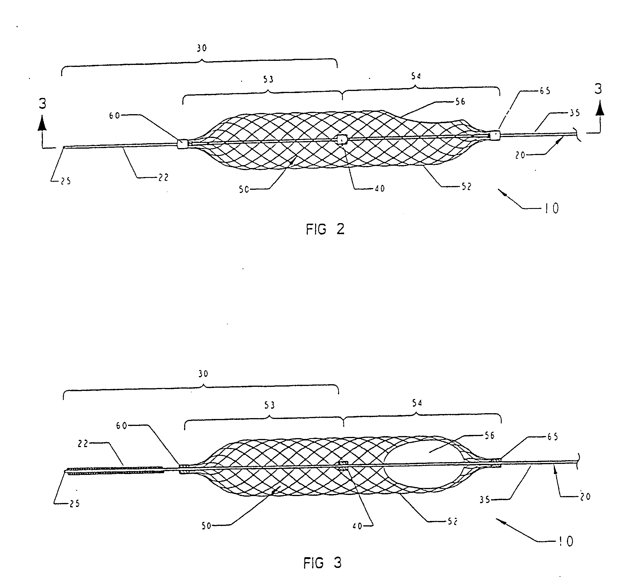
[0017]FIGS. 1-3 illustrate a filter system 10 in accordance with one embodiment of the invention. This filter system can be used in any channel in a patient's body, including blood vessels, the urinary tract or biliary tract and airways. This filter system 10 is optimally designed to be deployed in a patient's vessel in a minimally invasive procedure, such as by introducing the filter system into a blood vessel through a catheter (as described in greater detail below).

[0018] The filter system 10 of the invention generally includes a mandrel 20 and a filter 50. Conceptually, the mandrel 20 can be thought of as having a primary function of positioning and controlling the deployment of the filter 50 while the filter can be considered the primary therapeutic or functional element of the system 10.

[0019] The mandrel 20 should be fairly flexible to allow the device to be deployed in a curving body passageway without kinking or otherwise inhibiting suitable deployment of the filter 50. W...


PUM


Abstract

The present invention provides a method of deploying a medical filter within a channel in a patient's body and filter systems which can be used in such a method. Such a filter may include a radially expandable body 52 having an opening 56 in a proximal length thereof. In one method, the filter is urged along a length of the channel with the filter body in a radially reduced configuration. This body is expanded to substantially fill the lumen of the vessel and orient the opening in the body proximally. Body fluid is permitted to enter the filter body through the proximally oriented opening and pass distally through the distal length of the body so that the distal length of the body filters from the body fluid particulate material entrained therein. The proximal length of the body can be drawn into the retrieval catheter, thereby effectively closing the proximally oriented opening within the catheter to retain the particulate material within the enclosure. In a preferred embodiment, the filter body 52 is formed of a porous, resilient fabric having pores therein and the proximal opening 56 is at least five times the size of such pores.

Description

FIELD OF THE INVENTION [0001] The present invention generally relates to filters for body passageways, and has particular utility in connection with temporary vascular filters. BACKGROUND OF THE INVENTION [0002] Filters can be deployed in channels or vessels in patient's bodies in a variety of medical procedures or in treating certain conditions. For example, rotating burrs are used in removing atheroma from the lumen of patients' blood vessels. These burrs can effectively dislodge the atheroma, but the dislodged material will simply float downstream with the flow of blood through the vessel. Filters can be used to capture such dislodged material before it is allowed to drift too far downstream, possibly occluding blood flow through a more narrow vessel. [0003] Some researchers have proposed various traps or filters for capturing the particulate matter released or created in such procedures. However, most such filters generally have not proven to be exceptionally effective in actual...

Claims


Application Information

Patent Timeline
Patent Type & Authority Applications(United States)
IPC IPC(8): A61M29/00A61B17/00A61B17/22A61F2/01
CPCA61F2230/0069A61F2002/018A61F2230/0006A61F2/013A61F2002/016A61F2/01A61B17/221A61B2017/2212A61F2/0108
Inventor KUSLEIKA, RICHARD S.FINANDER, BRIAN V.
Owner EV3
Why Eureka
Try Eureka