Flanged graft with trim lines

Active Publication Date: 2007-01-04
CR BARD INC
View PDF99 Cites 25 Cited by
  • Summary
  • Abstract
  • Description
  • Claims
  • Application Information

AI Technical Summary

Benefits of technology

[0007] Accordingly, described herein is a vascular graft configured to offer optimal geometry for the anastomosis as a function of hemodynamic properties. By optimizing blood flow

Problems solved by technology

In particular, hemodynamic phenomena may induce the development of intimal hyperplasia, e.g., occlusive legions that are predominately located at a venous a

Method used


Image

  • Flanged graft with trim lines
  • Flanged graft with trim lines
  • Flanged graft with trim lines

Examples


Embodiment Construction

in conjunction with the accompanying drawings that are first briefly described.

BRIEF DESCRIPTION OF THE DRAWINGS

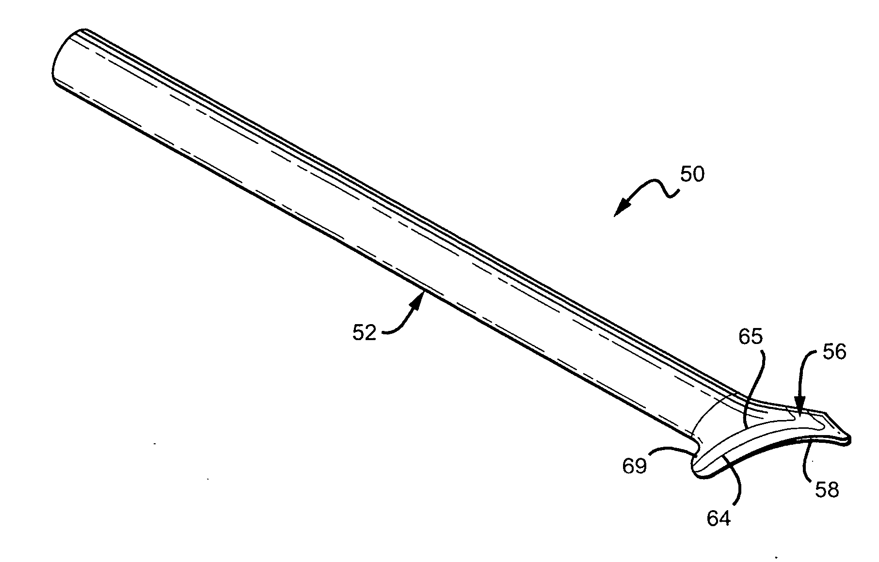
[0019]FIG. 1 is a perspective view of one embodiment of a vascular cuff graft with trim lines.

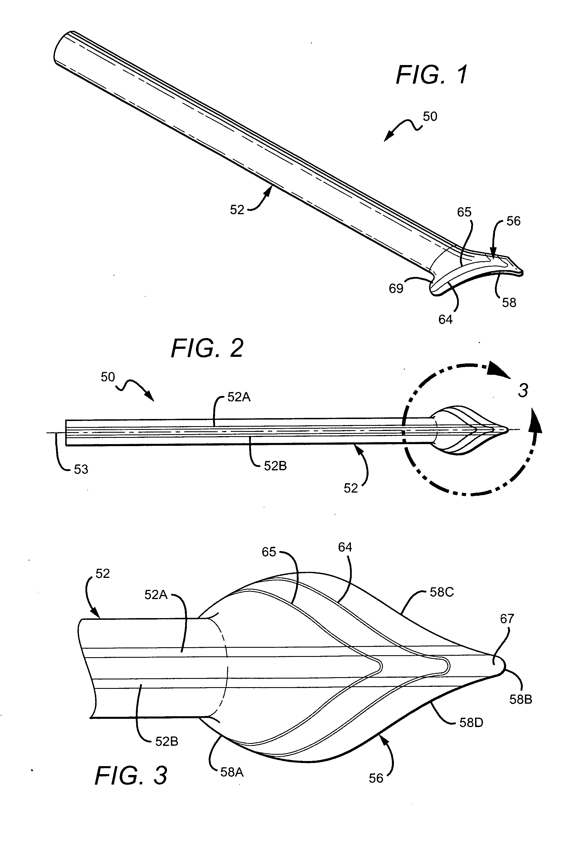
[0020]FIG. 2 is a top view of the vascular cuff graft of FIG. 1

[0021]FIG. 3 is an enlarged view of the cuff of the vascular cuff graft shown in FIG. 2.

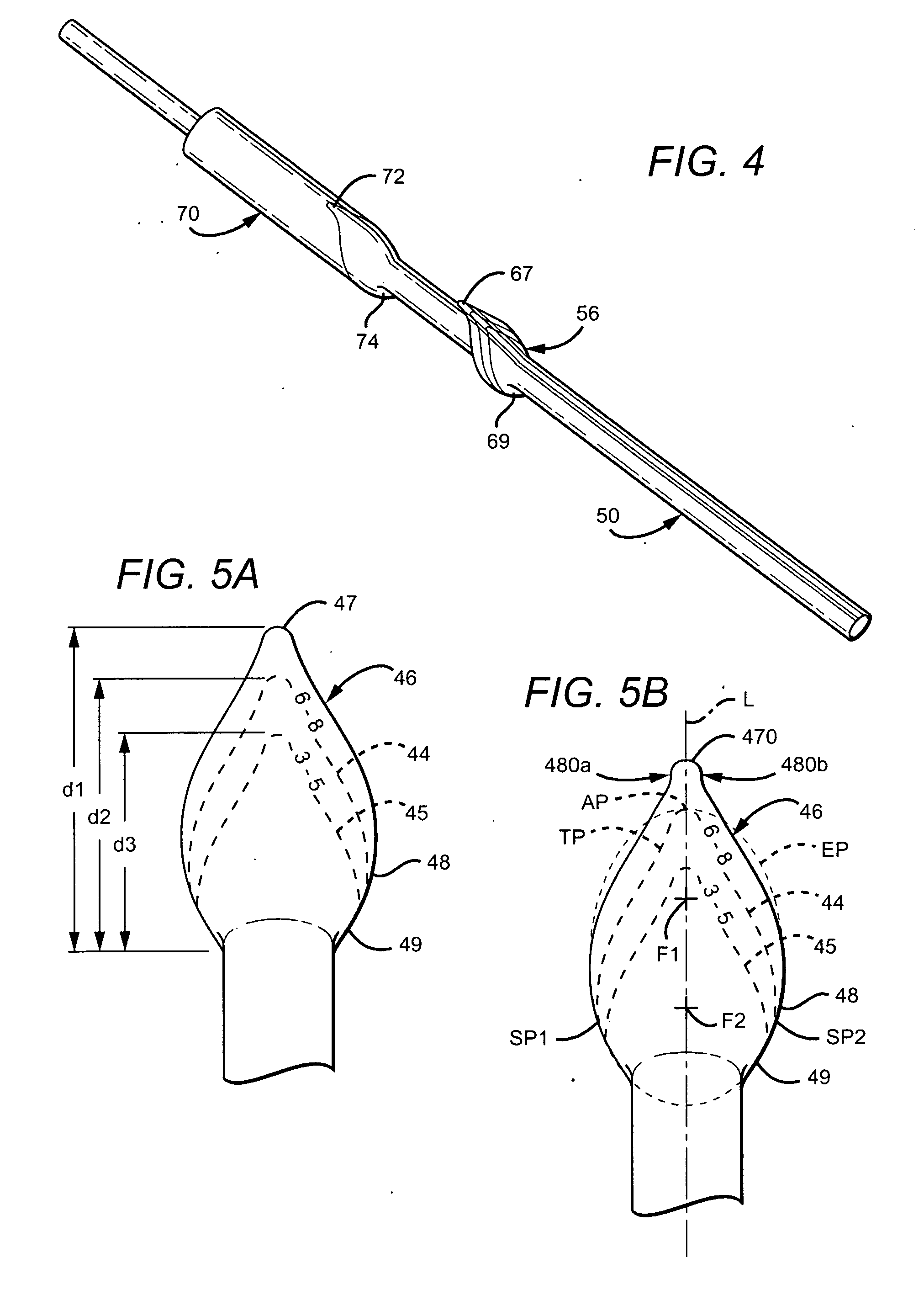
[0022]FIG. 4 is a perspective view of the vascular cuff graft of FIG. 1 disposed over a section of a mold.

[0023]FIG. 5A is a top view of another embodiment of a vascular cuff graft with trim lines.

[0024]FIG. 5B is a top view of another embodiment of a vascular cuff graft with trim lines.

[0025]FIG. 6A is a side view of another embodiment of a vascular cuff graft with trim lines.

[0026]FIG. 6B is a top view of the vascular cuff graft of FIG. 6A.

[0027]FIG. 7A is one embodiment of a template for disposition over a cuff of a vascular cuff graft.

[0028]FIG. 7B is another embodiment of a template for disposition over a cuff of a vas...


PUM

PropertyMeasurementUnit
Diameteraaaaaaaaaa
Sizeaaaaaaaaaa
Shapeaaaaaaaaaa

Abstract

A vascular graft with trim lines is described, the trim lines providing a guide for precision shaping of the cuff. The trim lines may be printed or otherwise disposed on a surface of the cuff or included on a template designed for disposition over the cuff. The trim lines may also be disposed on a side of a pocket into which the cuff is positioned for trimming. Also described is an apparatus and method for precise trimming of a vascular graft.

Description

PRIORITY [0001] This application claims the benefit under 35 U.S.C. § 119(e) to U.S. Provisional Application No. 60 / 695,406, filed Jul. 1, 2005, which is incorporated by reference into this application as if fully set forth herein.BACKGROUND OF THE INVENTION [0002] The use of vascular grafts for bypassing peripheral vascular occlusive conditions is believed to be well known, as is the use of microporous expanded polytetrafluoroethylene (ePTFE) in prosthetic vascular grafts. U.S. Pat. No. 6,436,135 to Goldfarb shows and describes an ePTFE prosthetic vascular graft; U.S. Pat. No. 6,273,912 to Scholz et al. shows and describes a flanged graft for end-to-side anastomosis; U.S. Pat. No. 6,190,590 to Randall et al. shows and describes an apparatus and method for making flanged grafts for end-to-side anastomosis; and the publication entitled, “Venaflo™ Vascular Grafts, Information for Use” shows an ePTFE graft with a modified venous end, each of which is incorporated by reference into this...

Claims


Application Information

Patent Timeline
IPC IPC(8): A61F2/06
CPCA61F2/06A61F2/07A61F2250/0039A61F2240/005Y10T83/75
Inventor SCHOLZ, HANSMCDERMOTT, JOHNCARR, ROBERTBEBB, DEBRA
Owner CR BARD INC
Why Eureka
Try Eureka