

Design support method and design support system
a support method and design technology, applied in the direction of cad techniques, stochastic cad, instruments, etc., can solve the problems of inability to use the results of techniques together as a database to solve problems, and the potential failure of assembling parts, etc., to achieve the effect of easy decision
- Summary
- Abstract
- Description
- Claims
- Application Information
AI Technical Summary
Benefits of technology
Problems solved by technology
Method used
Image

Examples
first embodiment
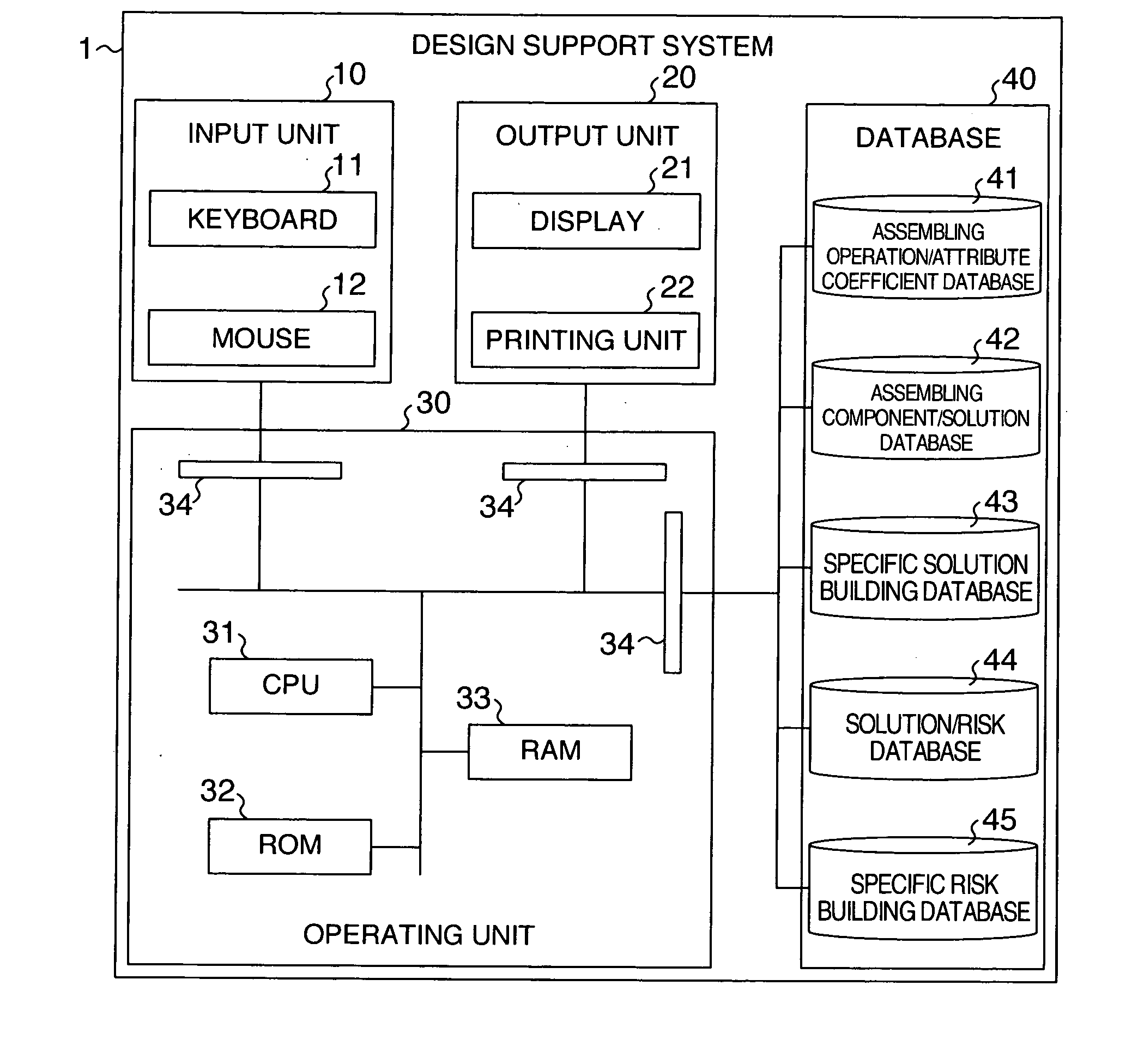
[0045]FIG. 1 is a configuration diagram showing a design support system according to the present invention. In FIG. 1, the reference numeral 1 represents a design support system; 10, an input unit; 11, a keyboard; 12, a mouse; 20, an output unit; 21, a display; 22, a printing unit; 30, an operating unit; 31, a CPU (Central Processing Unit); 32, a ROM (Read Only Memory); 33, a RAM (Random Access Memory); 34, an input / output portion; 40, a database portion; 41, an assembling operation / coefficient attribute database; 42, an assembling component / solution database; 43, a specific solution building database; 44, a solution / risk database; and 45, a specific risk building database.
[0046] InFIG. 1, the design support system according to this embodiment is constituted by the input unit 10, the output unit 20, the operating unit 30 and the database portion 40. The input unit 10 consists of the keyboard 11, the mouse 12, etc, and the output unit 20 consists of the display 21, the printing unit ...
second embodiment
[0128]FIG. 13 is a flow chart showing a design support method for use in the design support system shown in FIG. 1.
[0129] In FIG. 13, Steps S807-S811 in the first embodiment of the design support method shown in FIG. 8 are omitted in the second embodiment of the design support method. In this case, in Step S813, specific risks are displayed for all the specific solutions built in Step S806. The designer may select an effective specific solution from all the specific solutions and evaluate risk about the selected effective specific solution.
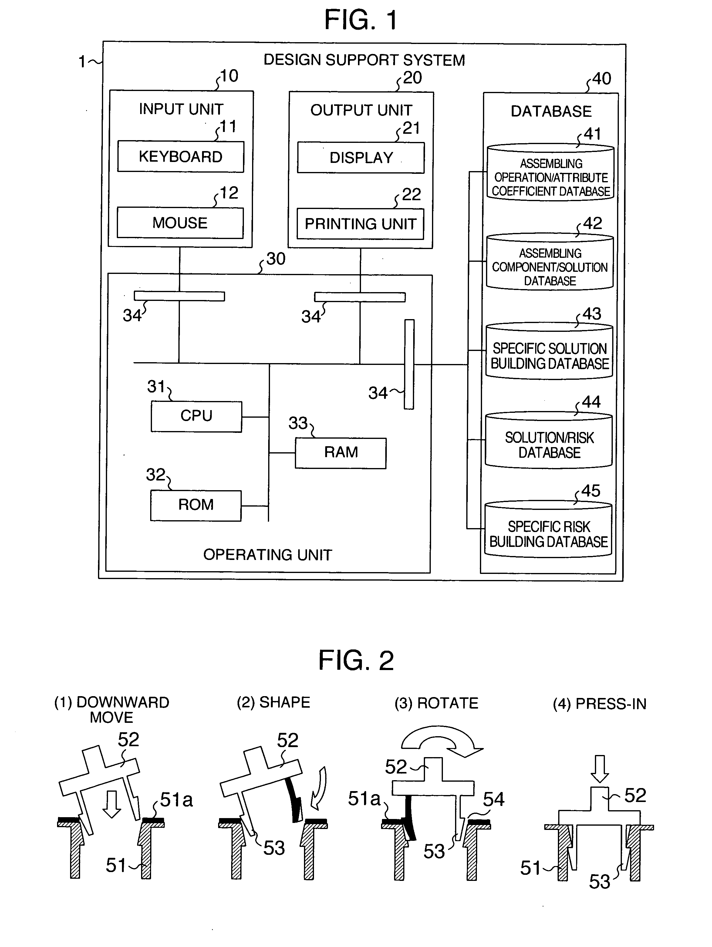
[0130]FIG. 14 is a configuration diagram showing the second embodiment of the design support system according to the present invention. FIG. 15 is a flow chart showing a specific example of a method for creating each database in FIG. 14. In FIG. 15, the case example of designing shown in FIG. 2 is used as an example. In FIG. 15, the reference numeral 47 represents an optimum solution decision database; and 48 represents an optimum solution extrac...
third embodiment
[0133]FIG. 16 is a flow chart showing a design support method according to the present invention carried out in accordance with the optimum solution extraction algorism shown in FIG. 15 using the case example of designing shown in FIG. 2 by way of example. Steps S801-S813 are similar to those of the flow chart shown in FIG. 8, so that their description will be omitted.
[0134] In the third embodiment, of the specific solutions obtained in Steps S801-S813 shown in FIG. 8 and displayed on the display 21, an optimum solution is decided or extracted (Step S814 or S821) by the optimum solution extraction algorism 48 using the optimum solution decision database 47 and based on evaluation of risks and restraining conditions. The restraining conditions for executing solutions are categorized into necessary restraining conditions which should be satisfied by the solutions and desired restraining conditions which the solutions are desired to satisfy.
[0135] In FIG. 16, specific risks are built ...
PUM
 Abstract
Description
Claims
Application Information