
Ionizer

a technology of generating apparatus and ionizer, which is applied in the direction of corona discharge, hair cleaning, hair drying, etc., can solve the problems of reducing the performance of electrostatic charge removal or the like, affecting the stability of ion balance, and unable to smoothly manufacture or assemble electronic parts, etc., to achieve further stabilization of ion balance and stabilize ion balance

Inactive Publication Date: 2007-01-11
KOGANEI
View PDF2 Cites 49 Cited by
  • Summary
  • Abstract
  • Description
  • Claims
  • Application Information

AI Technical Summary

Benefits of technology

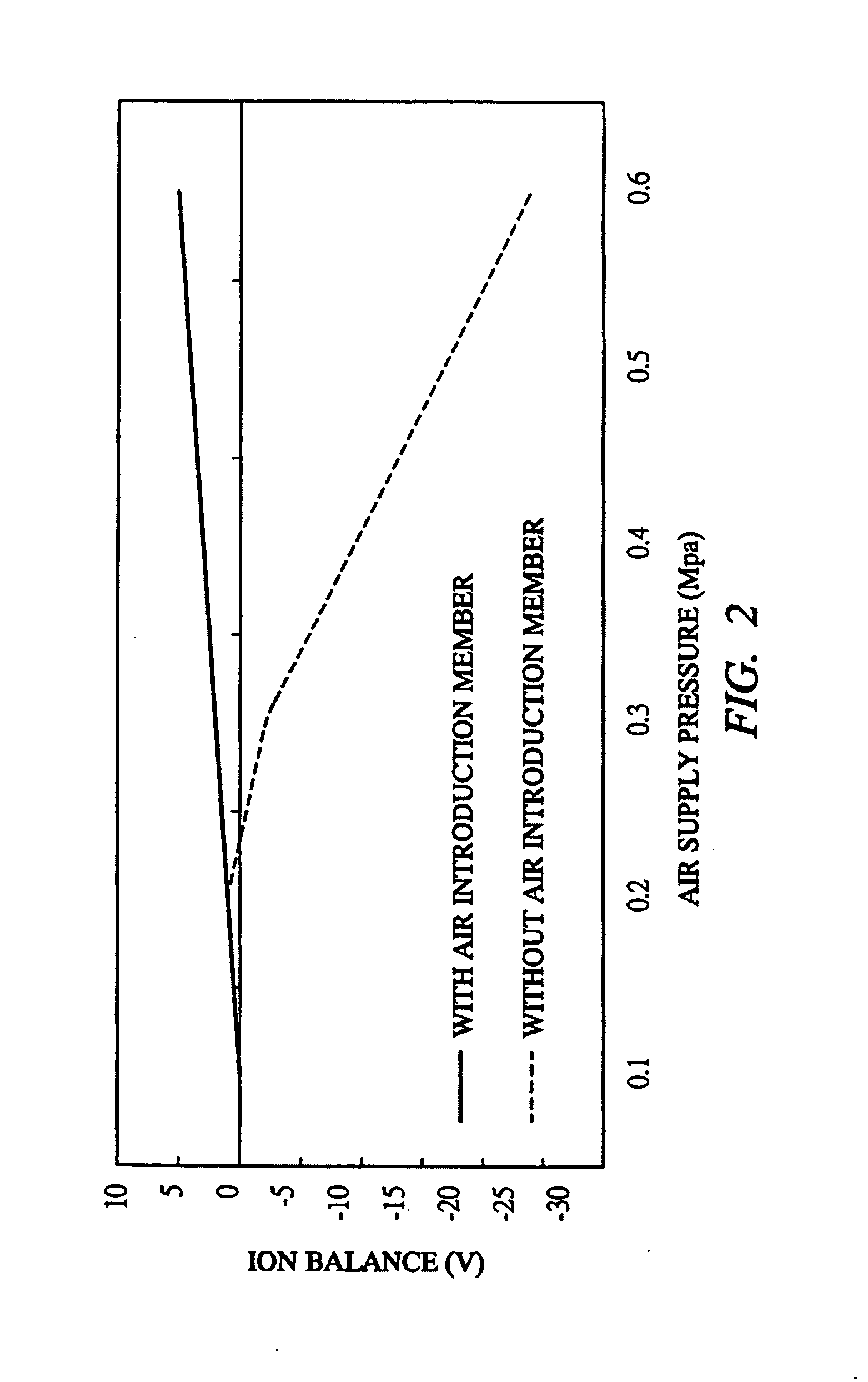
The present invention relates to an ion generating apparatus that can stabilize the ion balance without changing pressure or flow rate in the corona generating region. The apparatus includes a conductor blow tube, a discharge electrode, and a transfer fluid guiding member. The transfer fluid guiding member biases and guides the air flow on an outer circumference side so as not to rush directly against the corona generating region. This results in a stable ion balance even when a large amount of ionized air is generated. The apparatus also divides the air flow and biases and guides the divided air flows in a side direction of the entire discharge electrode and the corona generating region so as not to rush not directly against the corona generating region. This further stabilizes the ion balance.

Problems solved by technology

In manufacturing or assembling electronic parts such as semiconductor chips, if static electricity is generated in the electronic parts or jigs for manufacturing and assembling the same, it is not possible to smoothly manufacture or assemble the electronic parts.
However, in order to generate a large amount of ionized air, an increase of a flow rate of air in the air flow passage becomes necessary, whereby the pressure or flow rate in the air flow passage is increased, which results in any fear of making the corona discharge around the discharge electrode unstable.
As described above, when the corona discharge becomes unstable, a ratio of positive ions to negative ions, that is, an ion balance is easily biased also in the ionized air generated and thus there is the problem that electrostatic charge removal performance or the like is reduced.

Method used


Image

  • Ionizer
  • Ionizer
  • Ionizer

Examples


Embodiment Construction

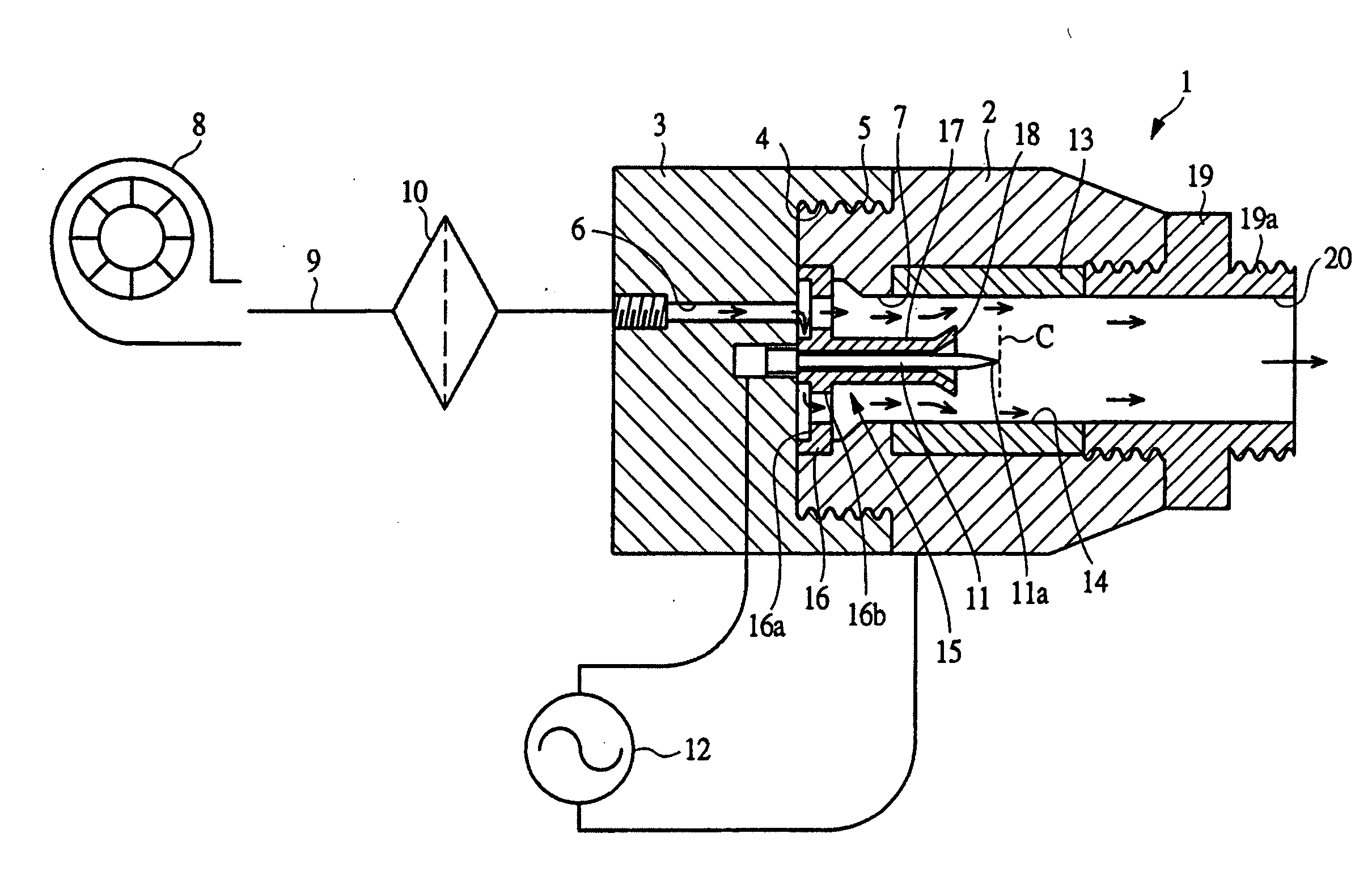
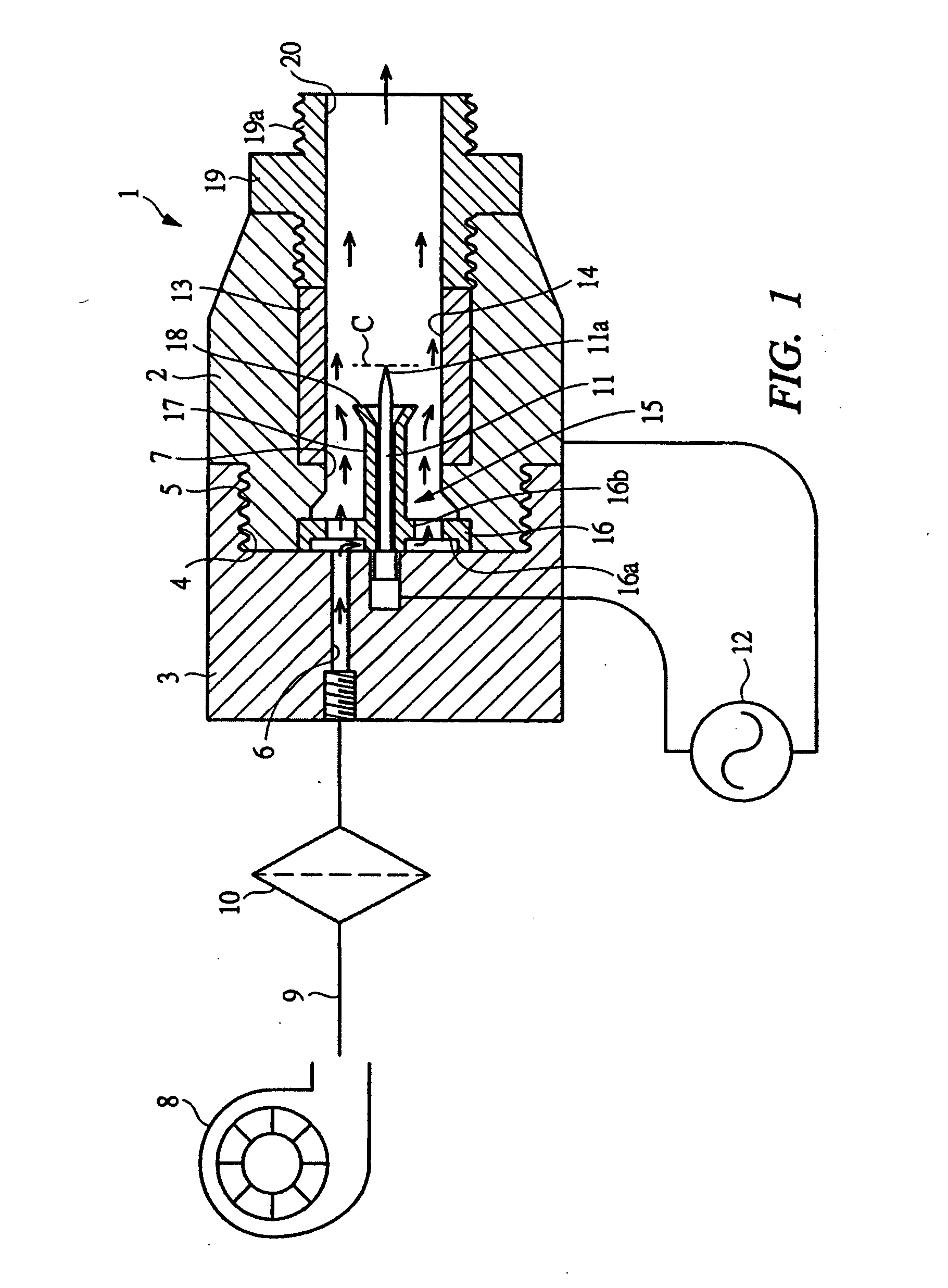
[0018] Hereinafter, embodiments of the present invention will be detailed based on the drawings. FIG. 1 is a schematic sectional view showing an ion generating apparatus according to one embodiment of the present invention. The ion generating apparatus according to the present embodiment is an apparatus for generating ionized air by using atmospheric air as transfer fluid, and is of a blow type in which the ionized air generated can be locally injected to a predetermined place through a pipe type nozzle or the like.

[0019] As shown in FIG. 1, an ion generating apparatus 1 has an apparatus body 3 on which a head 2 made of a conductor such as a metal or conductive material is detachably mounted. The apparatus body 3 is made of an insulating material such as a resin or ceramic, and a male screw portion 5 to be screwed and connected into a screw hole 4 formed in the apparatus body 3 is formed at the head 2 serving as a conductor blow tube. The head 2 is hollow and has a through hole 7 w...


PUM


Abstract

A head 2 has a through hole 7 into which compressed air is supplied and flows, and a discharge electrode 11 is disposed inside the through hole 7. When a voltage required for discharging is applied to the head 2 made of a conductor and the discharge electrode 11, a corona C is generated at a tip end 11a of the discharge electrode 11, whereby flowing air is ionized. By a cylindrical housing tube portion 17 made of an insulator and receiving most of the discharge electrode 11 and a tapered guide portion (transfer fluid guiding member) 18 formed at a downstream-side end thereof, an air flow is biased and guided on a side of an outer circumference thereof so as not to rush directly against the corona generating region. Thus, even when air supply pressure is increased, an ion balance can be stabilized without almost changing pressure or a flow rate in the corona generating region.

Description

TECHNICAL FIELD [0001] The present invention relates to an ion generating apparatus for generating ionized air used for removing static electricity from various members such as electronic parts. BACKGROUND ART [0002] In manufacturing or assembling electronic parts such as semiconductor chips, if static electricity is generated in the electronic parts or jigs for manufacturing and assembling the same, it is not possible to smoothly manufacture or assemble the electronic parts. Thus, an ion generating apparatus also called an ionizer or ion generator is used to blow air which has been subjected to ionization, i.e., ionized air to members requiring removal of electrostatic charge. The members which require electrostatic charge removal, namely, removal of static electricity include a pipe for guiding air or liquid and an operating portion in a machine such as a robot or parts feeder, in addition to the aforementioned electronic parts. The ionized air is supplied to surfaces of such memb...

Claims


Application Information

Patent Timeline
Patent Type & Authority Applications(United States)
IPC IPC(8): A45D20/12H01T19/00H01T19/04H01T23/00
CPCH01T23/00H01T19/00H01T19/04
Inventor KOTSUJI, KAZUO
Owner KOGANEI
Learn More