Throttle valve adjusting device

Inactive Publication Date: 2007-01-11
PIERBURG GMBH & CO KG NEUSS
View PDF10 Cites 4 Cited by
  • Summary
  • Abstract
  • Description
  • Claims
  • Application Information

AI Technical Summary

Benefits of technology

[0023] In another alternative embodiment, the torsional strength of the pole tube is produced by means of a screw connection between the pole tube and the contact plate. Thus, the shaping of the pole tube or the contact plate is simplified, and the tolerances to be maintained can be selected to be larger.
[0024] Thus, in accordance with the present invention, a valve adjusting device is made available in which

Problems solved by technology

While finishing work on the throttle valve housing is omitted, the assembly of such a device is distinctly more complicated.
In particular, the linkings of the motor, the gear center wheel axle, and the bearing for the throttle valve shaft to the element carrier require a high assembly expense.
Moreover, the throttle valve housing and the drive unit are not independent so that the

Method used


Image

  • Throttle valve adjusting device
  • Throttle valve adjusting device
  • Throttle valve adjusting device

Examples


Embodiment Construction

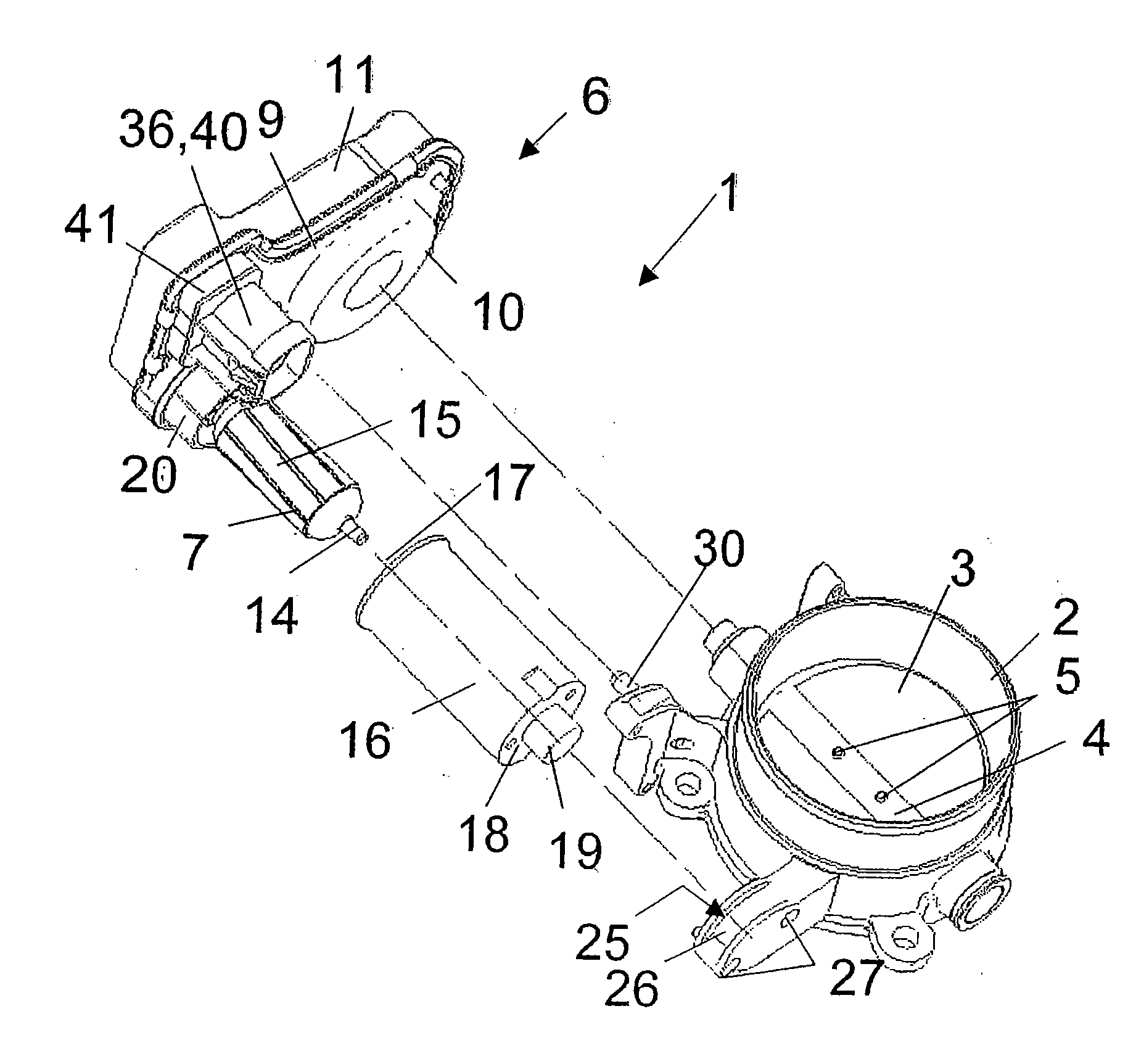
[0030] The exemplary embodiment shown in the Figures of a valve adjusting device 1, according to the invention, comprises a valve housing 2, in which a valve 3 is fixed on a shaft 4 via screws 5. The valve shaft 4 can thereby be caused to rotate via a drive unit 6, so that the valve body 3 opens a duct cross-section of varying size in the housing 2.

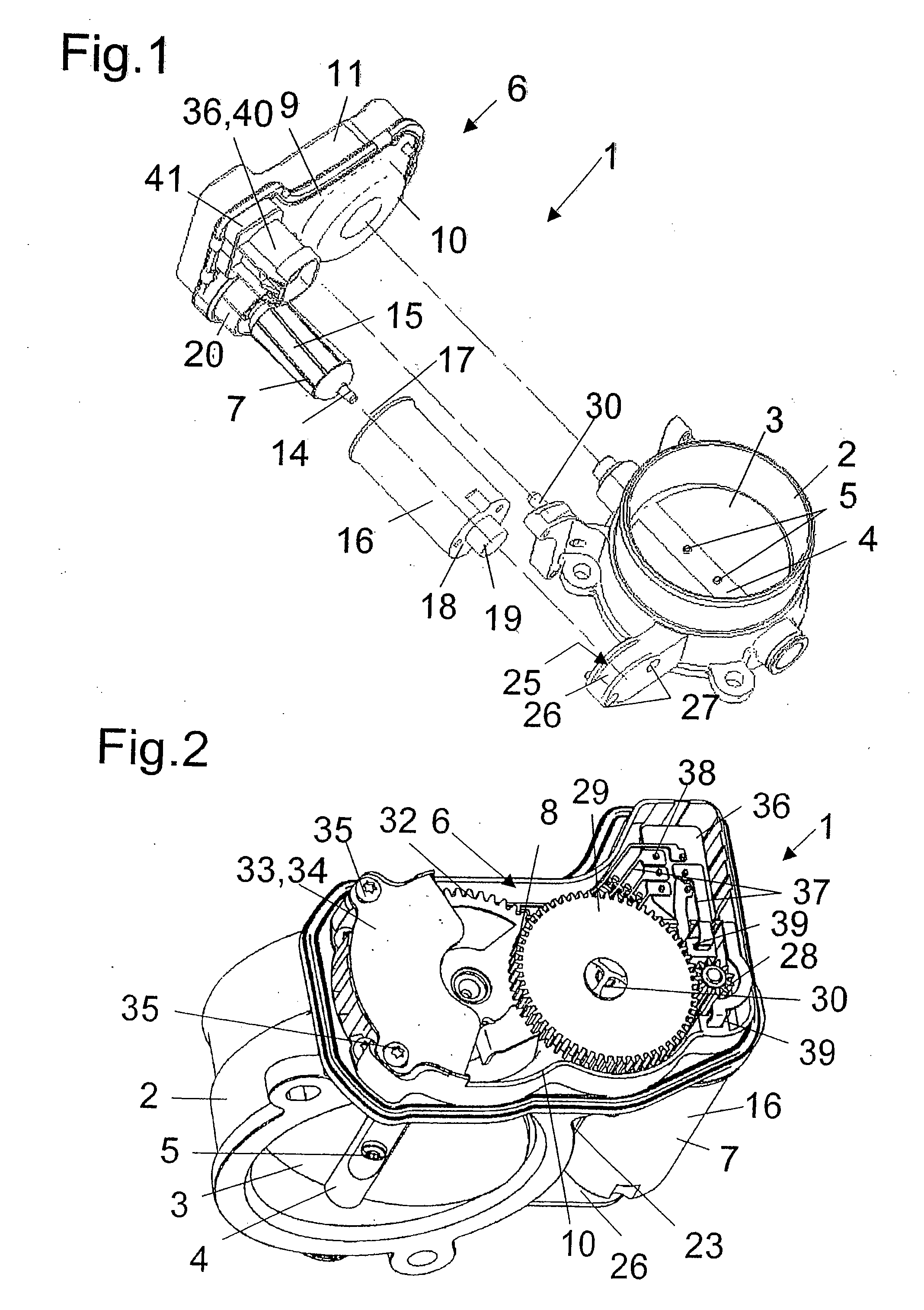
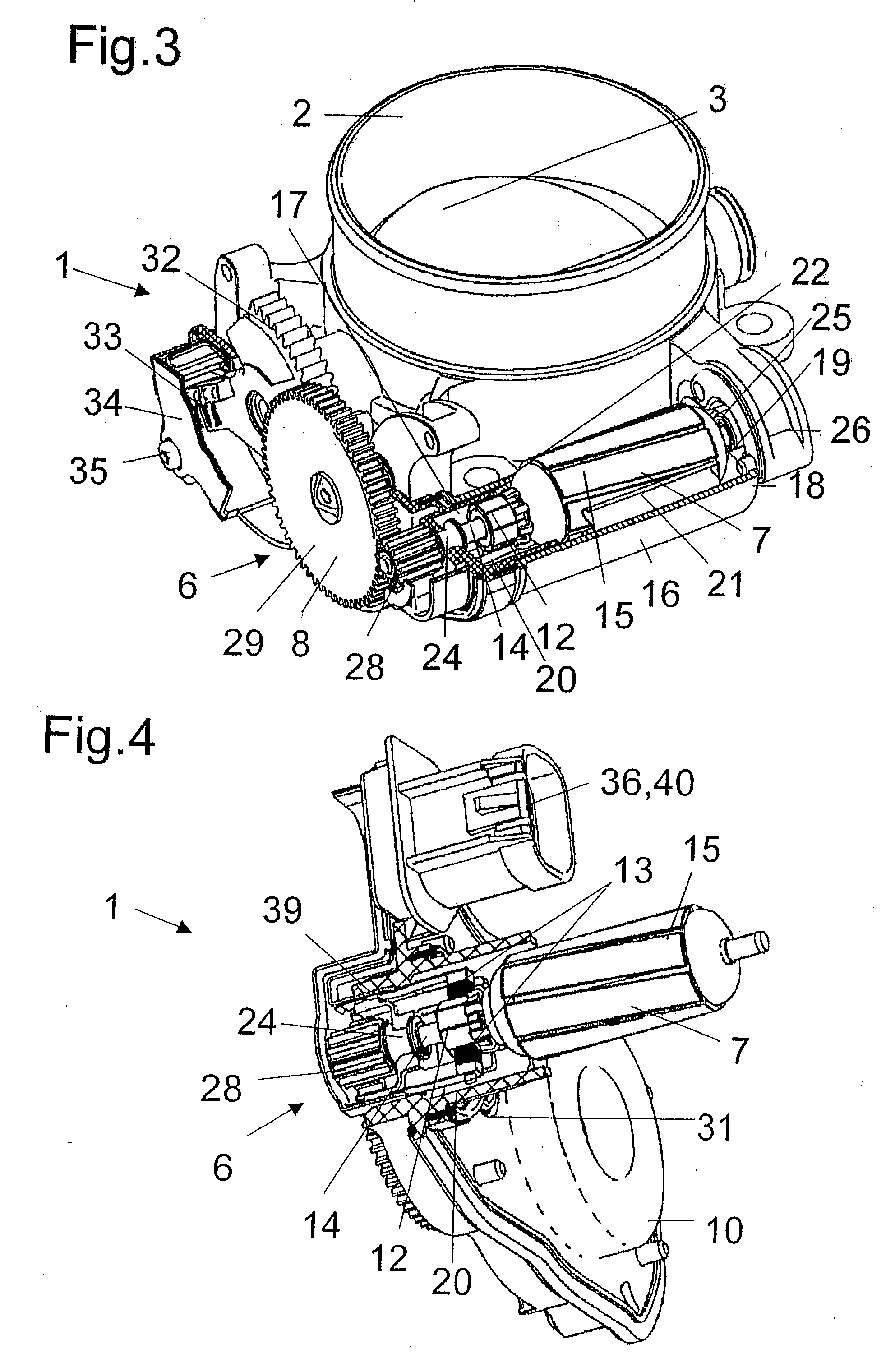
[0031] As shown in FIGS. 1 and 2, the drive unit 6 comprises an electric motor 7 that is in operative connection with the valve shaft 4 via a reduction gear 8. The reduction gear 8 is arranged in a housing 9 that essentially comprises a contact plate 10 and a cover 11 that essentially seals the contact plate tightly.

[0032] The electric motor 7 is embodied in the exemplary embodiment as a permanent magnet direct current motor and accordingly features a collector 12 that is in operative connection with brush springs 13, via which the electrical contacting takes place in a known manner. The construction of the electric motor 7 can be seen ...


PUM


Abstract

The invention relates to a throttle valve adjusting device (1) which comprises a throttle valve housing (2) linked with a drive unit (6). According to the invention, the electric motor (7) of said drive unit (6) is disposed both outside the housing (9) of the drive unit (6) and outside the throttle valve housing (2) so that its pole tube (16) lies substantially exposed and at the same time serves as the motor casing. Said pole tube (16) has a closed (18) and an open end (17) which is closed by a contact plate (10), while the closed end (18) comprises a bearing element (19) for the drive shaft (14) of the electric motor (7). The inventive throttle valve housing is improved in terms of construction space required and materials used, thereby considerably reducing the costs for production and assembly as well as reducing its weight.

Description

[0001] This is a National Phase Application in the United States of International Patent Application No. PCT / EP2004 / 009425 filed Aug. 24, 2004, which claims priority on German Patent Application No. DE 103 41 396.0, filed Sep. 5, 2003. The entire disclosures of the above patent applications are hereby incorporated by reference. FIELD OF THE INVENTION [0002] The invention relates to a valve adjusting device, in particular a throttle valve adjusting device for combustion engines, with a valve housing that features a valve connected to a valve shaft, by which the valve is pivoted in the valve housing at least on one side, and with a drive unit that features at least one electric motor and a reduction gear to drive the valve, and a sensor for reporting the position of the valve adjustment, whereby at least the gear is arranged in a housing that features a contact plate fixed to the valve housing and a cover closing the housing. BACKGROUND OF THE INVENTION [0003] Various generic valve ad...

Claims


Application Information

Patent Timeline
IPC IPC(8): F02D11/10F02D9/10F16K1/22F16K31/04F16K31/53
CPCF02D9/1065F02D11/10F16K31/043F16K31/535F16K1/221
Inventor NEISE, RALFMUNICH, MARC-ANTON
Owner PIERBURG GMBH & CO KG NEUSS
Why Eureka
Try Eureka