Constant velocity joint

Inactive Publication Date: 2003-03-20
GM GLOBAL TECH OPERATIONS LLC +1
View PDF0 Cites 1 Cited by
  • Summary
  • Abstract
  • Description
  • Claims
  • Application Information

AI Technical Summary

Benefits of technology

0010] The present invention has the advantage of providing a compact constant velocity joint through elimination of the standard ball cage normally present to contain the balls but adding radially thickness to the joint assembly. By eliminating the ball cage, the overall radial size of the joint is decreased. Further, the subject cage-less con

Problems solved by technology

Reducing the thickness of any one or more of these components may impair the strength or integrity of the joint, and thus there is a limit to how small a conventional constant velocity joint can be made without detractin

Method used


Image

  • Constant velocity joint
  • Constant velocity joint
  • Constant velocity joint

Examples


first embodiment

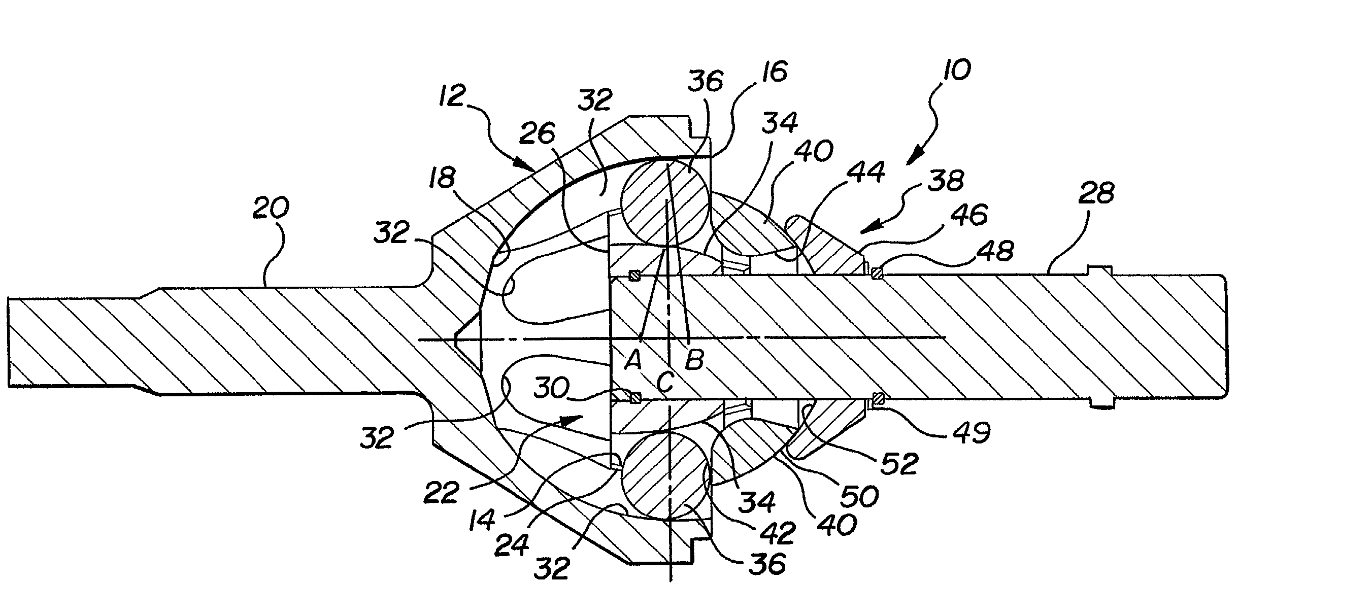
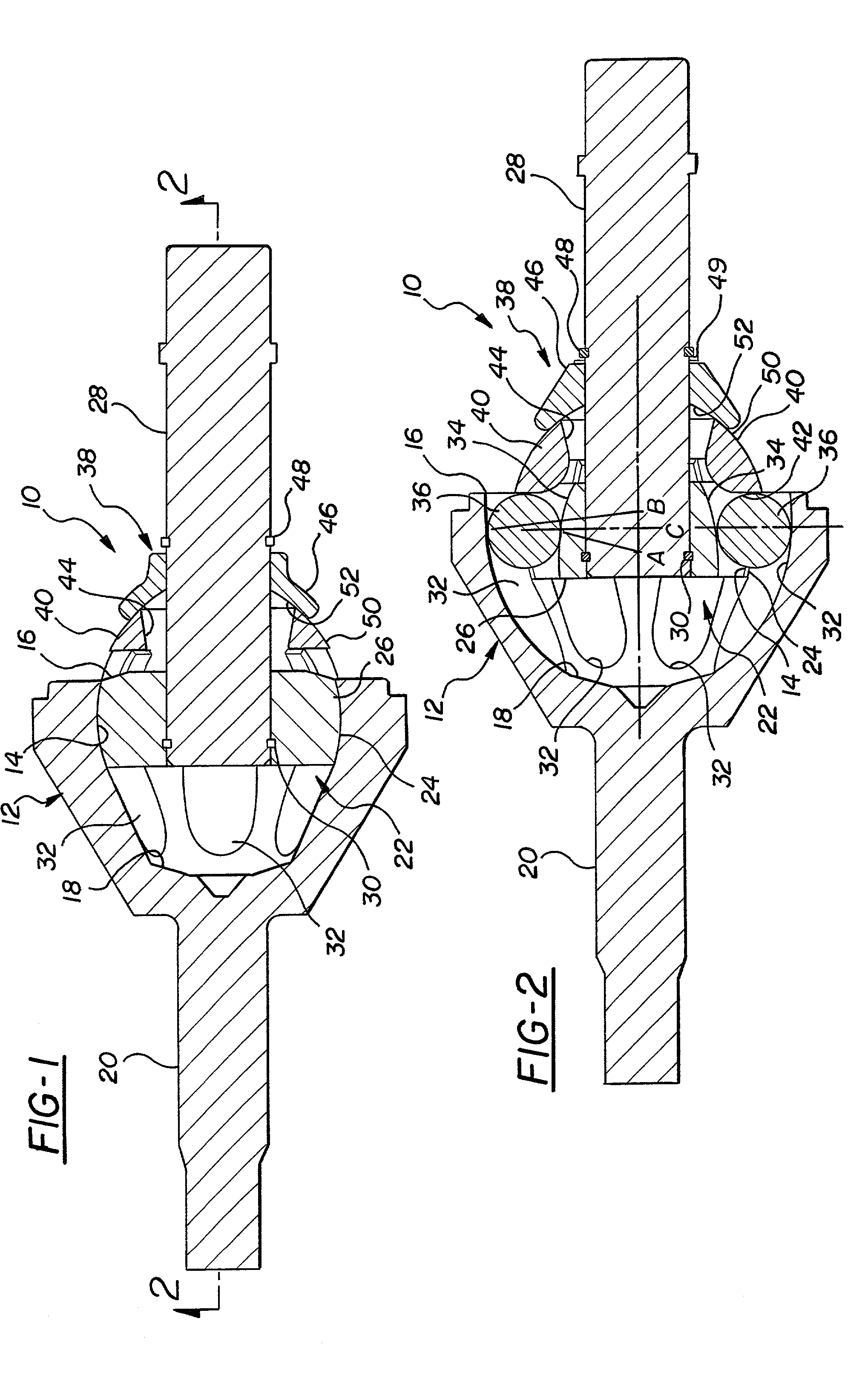
[0018] A constant velocity joint assembly constructed according to the invention is shown generally at 10 in FIGS. 1 and 2 and comprises an outer joint member or race 12 having an inner contact surface 14 which is preferably part-spherical. The outer joint member 12 has at least one open end 16 at one axial end of the joint. In the embodiment shown, the axially opposite end of the outer joint member 12 has a closed end 18 from which an axle 20 extends.

[0019] The joint assembly 10 includes an inner joint member generally indicated at 22 which is disposed at least partly within the outer joint member 12 and is formed with a part-spherical outer surface 24 that engages the complementing inner surface 14 of the outer joint member 12 to enable the outer 12 and inner 22 joint members to articulate about a common center C.

[0020] The inner joint member 22 includes an inner race portion 26 and an axle portion 28. The inner race portion 26 is disposed in contact with the outer joint member 12...

second embodiment

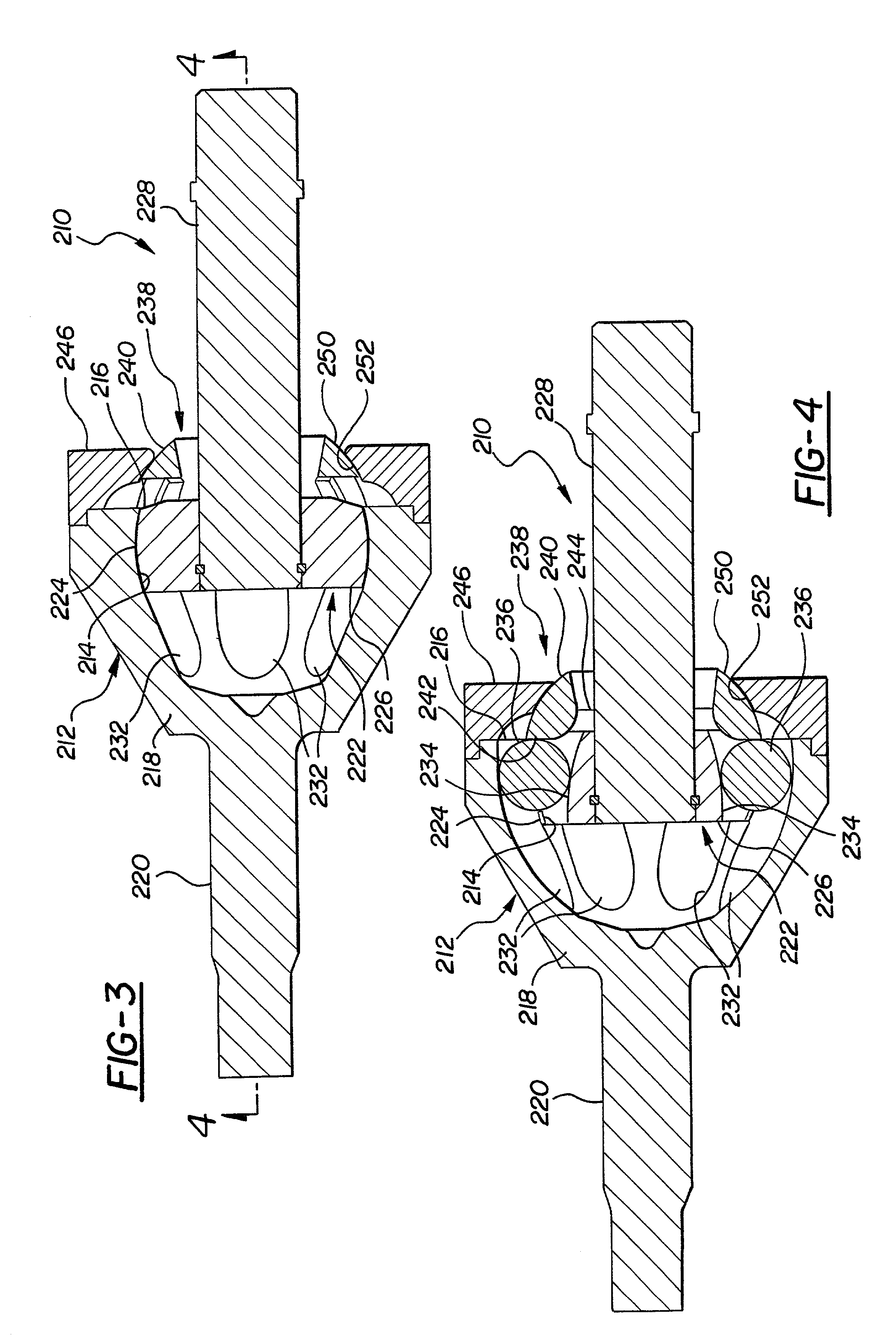
[0026] FIGS. 3 and 4 show an alternative embodiment of the invention, wherein the components and operation are identical except that the seat 46 is removed from the axle 28 and mounted on the outer joint member 12 as will be explained. For purposes of this second embodiment, the same reference numerals are used to designate like components, but are offset by 200.

[0027] The seat 246 of this alternative embodiment is in the form of an outer ring which is secured, either removably or permanently following installation of the inner joint member 22, to the outer joint member 12. The seat 246 has an inner surface 52 which engages the surface 50 of the partial cage 40 to provide articulated support to the partial cage 240 about the common center of the joint as before. The construction and method of assembly is otherwise identical, as is the operation of the joint. The seat 246 can be used in conjunction with the two piece or one piece inner joint member described above.

[0028] FIG. 6 shows...


PUM


Abstract

A compact constant velocity joint includes outer and inner joint members having surfaces to provide articulation of the joint. The surfaces are formed with aligned grooves to receive torque-transmitting balls. A ball retainer is provided axially adjacent the balls, adjacent an open end of the outer joint member to retain the balls in the grooves during operation. The ball retainer articulates on the same center point as that of the outer and inner joint members.

Description

[0001] 1. Technical Field[0002] This invention relates to constant velocity universal joints.[0003] 2. Related Art[0004] Constant velocity joints are used to transmit torque through an angle while maintaining constant velocity ratio between a driving and driven shaft member of the joint at all angles. A typical constant velocity joint includes an outer member formed with a part-spherical inner surface and a series of ball grooves, an inner member formed with a part-spherical outer surface and a series of complementing ball grooves aligned with the grooves of the outer joint member, a torque-transmitting ball disposed in each groove pair, and a ball cage disposed between the inner and outer joint members and having part-spherical surfaces and contact with those of the inner and outer joint members for articulation of the joint.[0005] The size of the joint is dependent in part on the angle to be achieved and the stack-up dimensions of the component parts, namely the inner joint part, ...

Claims


Application Information

Patent Timeline
IPC IPC(8): F16D3/223F16D3/2237
CPCF16D3/2237F16D2003/22303Y10S464/906
Inventor THOMAS, STEVEN MARKSKVARLA, WILLIAM PAUL
Owner GM GLOBAL TECH OPERATIONS LLC
Why Eureka
Try Eureka