
Pneumatic tire

Inactive Publication Date: 2007-01-11
TOYO TIRE & RUBBER CO LTD
View PDF8 Cites 3 Cited by
  • Summary
  • Abstract
  • Description
  • Claims
  • Application Information

AI Technical Summary

Benefits of technology

[0011] An object of the invention is to provide a pneumatic tire with a tread pattern including the novel cross grooves which has a superior noise control performance.
[0012] As a result of through studies made with a view to accomplishing the object, the inventors found that the object can be accomplished to reduce the level of noise by limiting the crossing angle of cross grooves to a specific range, managing to complete the invention successfully.
[0015] According to the invention, in the pneumatic tire with the tread pattern including the cross grooves, the pattern vibration noise can be reduced, and hence, the pneumatic tire can be provided which has a superior noise control performance. In addition, the pneumatic tire is such that the crossing angle is set to be within a predetermined range according to a position where the cross grooves are provided in order to reduce the pattern vibration noise, and since there is no need to change the void ratio which is a ratio of sea portions to land portions in the tread pattern, thereby making it possible to reduce the level of noise without sacrificing the water drainage properties.

Problems solved by technology

Irrespective of the aforesaid conventional methods, the reduction in pattern vibration noise is not easy in tread pattern configurations which make it difficult to adopt pitch arrangements which allow for an increase in the number of tire pitches and variable pitch lengths due to design limitations and other properties required for tires.
In the pattern configuration which adopts these cross grooves, since the length of a pitch in the circumferential direction of the tire becomes long, there is imposed a limitation on the number of pitches and setting of pitch arrangement.

Method used


Image

  • Pneumatic tire
  • Pneumatic tire
  • Pneumatic tire

Examples


examples 1 to 3

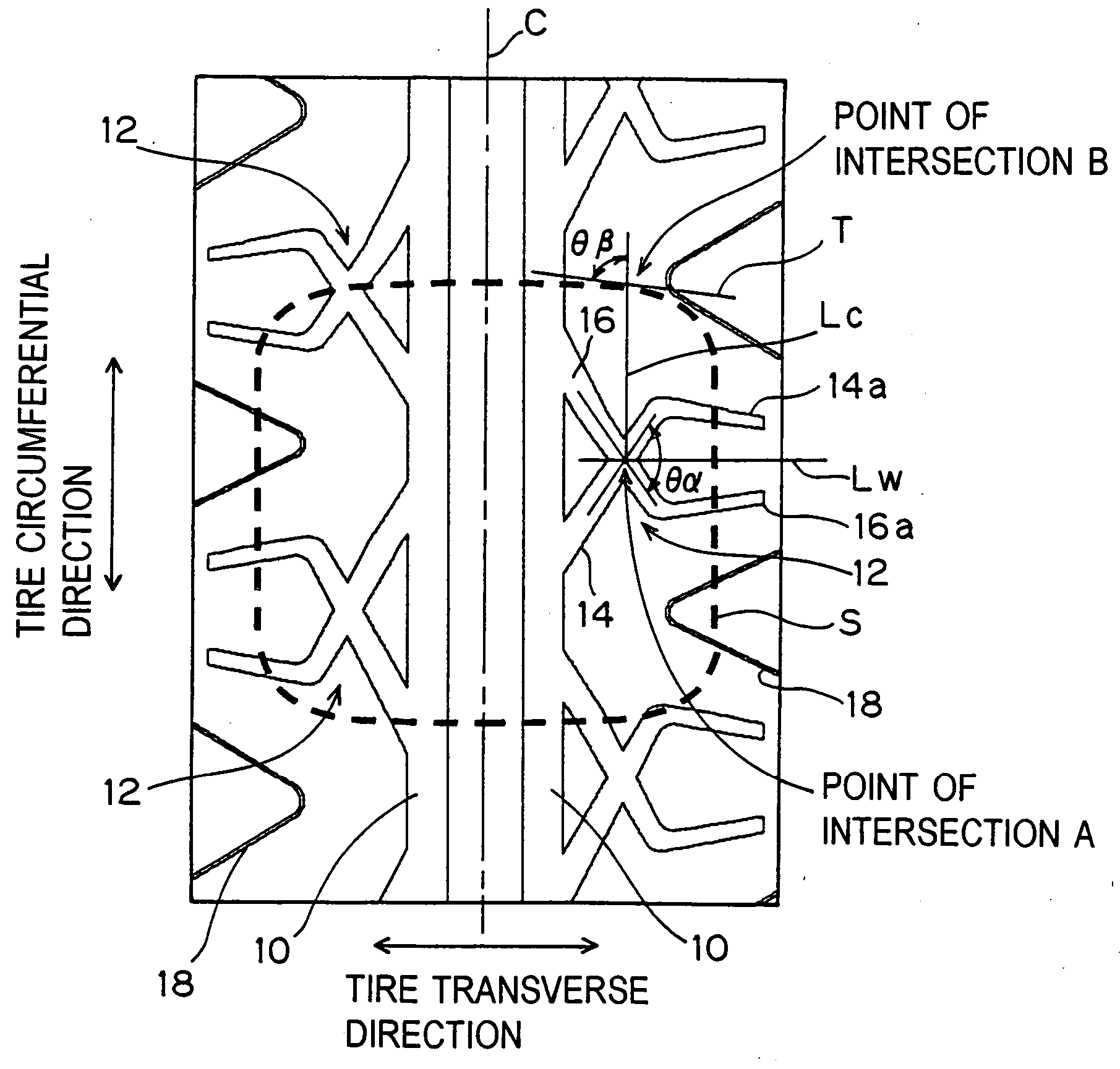
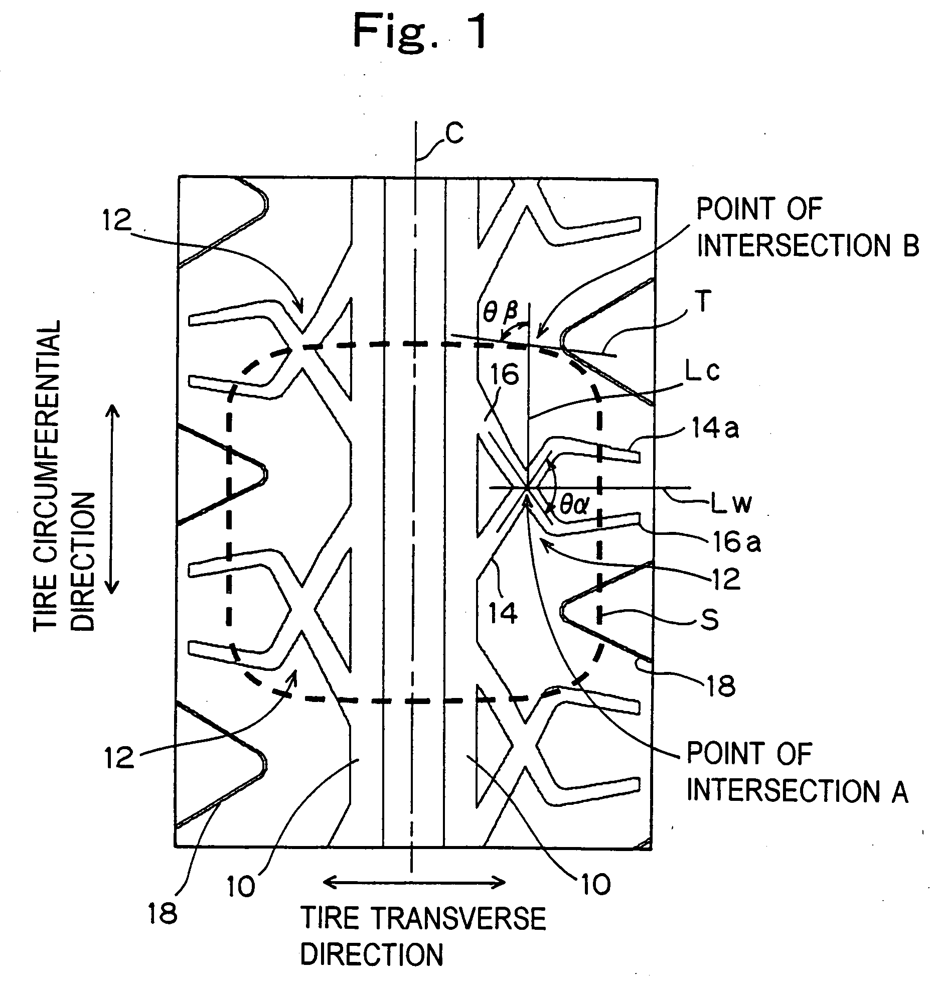
[0043] On the basis of the tread pattern shown in FIG. 1, pneumatic radial tires of Examples 1 to 3 and Comparison Examples 1 to 4 were prepared in which the distance between the point of intersection A and the tire transverse center line C was changed to thereby changes θβ as shown in Table 1 below, and θα was set as shown in Table 1, the other configurations remaining the same. A tire size used was 225 / 45R17.

[0044] The individual tires so obtained were measured with respect to water drainage properties and noise control performance using the following method.

[0045] Water Drainage Properties: the individual tires were mounted on a passenger car (sedan) of an engine displacement of 2500 cc, and the vehicle was run on a wet road surface with a water depth of 8 mm. An sensory evaluation was made on the existence of hydroplaning phenomenon during the running, and the results were evaluated using Example 1 as a base index of 100. A larger value means more superior water drainage prope...

examples 4 , 5

EXAMPLES 4, 5

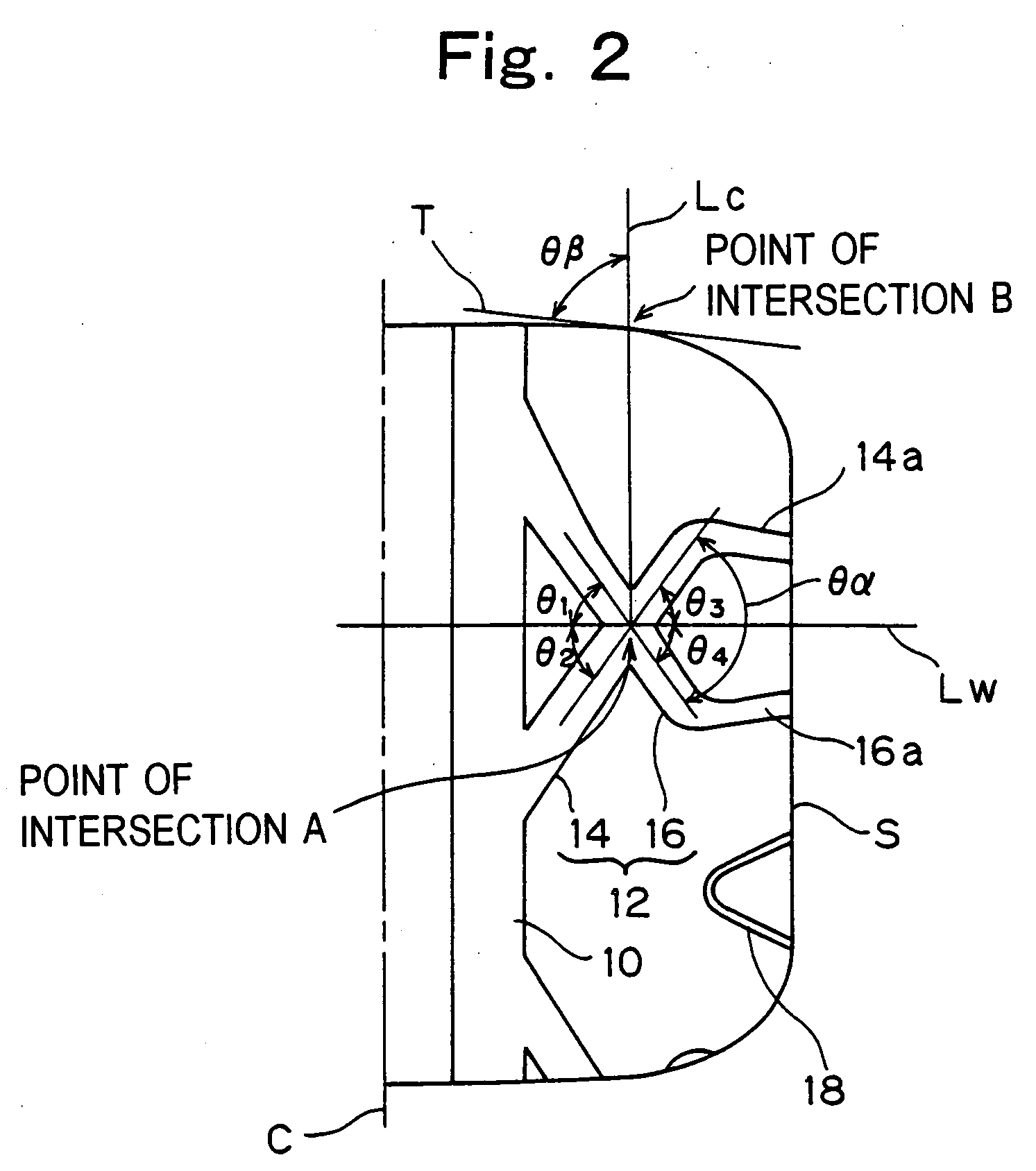
[0048] On the basis of the tread pattern shown in FIG. 6, pneumatic tires of Examples 4, 5 and Comparison Examples 5 to 7 were prepared in which θα and θβ were set as shown in Table 2 and the other configurations were the same. A tire size of 225 / 45ZR17 was used.

[0049] The individual tires so obtained were measured with respect to water drainage properties and noise control performance using the same method as that used for Examples 1 to 3. In addition, the water drainage properties were evaluated using Example 4 as a base index of 100. A larger value means more superior water drainage properties.

[0050] The results are shown in Table 2, and with Examples 4, 5 which were prepared according to the invention, the noise levels could be reduced without sacrificing the water drainage properties.

TABLE 2Distance betweenNoisePoint ofControlIntersection APerformanceand TireWaterPatterTransverseDrainageNoiseCenter Line (mm)θα(°)θβ(°)PropertiesLevel (dB)Example 455.0110.070.010...


PUM


Abstract

There is provided a pneumatic tire including cross grooves which are provided on a tread portion in such a manner as to cross each other in an X shape, as well as cross each other symmetrically with respect to a tire transverse line, wherein assuming that a point of intersection between a tire circumferential line which passes through a point of intersection A of the cross grooves and a tire contact patch shaping line is a point of intersection B, a crossing angle of the cross grooves which lie to hold therebetween a tire transverse line which passes through the point of intersection A is θα, and an angle made by a tire circumferential line which passes through the point of intersection B and a tangential line to the tire contact patch shaping line at the point of intersection B is θβ, the cross grooves satisfy the following conditions: when θβ<45°, θα<−2.5×θβ+162.5°  1) when 45°≦θβ<60°, θα>−1.2×θβ+179°  2) when 60°≦θβ≦90°, θα>105°.   3)

Description

CROSS-REFERENCE TO RELATED APPLICATIONS [0001] This application is based upon and claims the benefit of priority from the prior Japanese Patent Application No. 2005-172709, filed on Jun. 13, 2005; the entire contents of which are incorporated herein by reference. BACKGROUND OF THE INVENTION [0002] 1. Field of the Invention [0003] The present invention relates to a pneumatic tire, and more particularly to a pneumatic tire with a tread pattern having a superior noise control performance. [0004] 2. Description of the Related Art [0005] As one of causes for pneumatic tire noise generated while running, there has been known a so-called pattern noise such as pumping noise, pattern vibration noise and the like. When grooves formed on a tread of a tire to make up a tread pattern enter a contact patch area, air is trapped and compressed in the grooves, and when the grooves leave the contact patch area, the air so trapped and compressed in the grooves is released. The pumping noise is a noise...

Claims


Application Information

Patent Timeline
IPC IPC(8): B60C11/00
CPCB60C11/0306B60C11/0332B60C2011/0374B60C2011/0388B60C11/0304
Inventor SHIMA, ICHIRODOAN, VAN QUANG
Owner TOYO TIRE & RUBBER CO LTD
Features
  • Generate Ideas
  • Intellectual Property
  • Life Sciences
  • Materials
  • Tech Scout
  • Unparalleled Data Quality
  • Higher Quality Content
  • 60% Fewer Hallucinations
Learn More