Tag multiplication

a multi-tag technology, applied in the field of wireless communication, can solve the problems of limiting the effective communication range of the reader/tag transponder, defeating the primary purpose of establishing the service point, and affecting the operation of the burglar alarm, so as to facilitate communication, extend the effective communication range of the machine-readable passive tag, and protect the system

Active Publication Date: 2007-01-11
III HLDG 3
View PDF8 Cites 234 Cited by
  • Summary
  • Abstract
  • Description
  • Claims
  • Application Information

AI Technical Summary

Benefits of technology

[0017] The present invention includes an apparatus, method, program and system for extending the effective communication range of a machine-readable passive tag. The system

Problems solved by technology

While cellular networks like GSM provide a global means for transmitting and receiving data, due to cost, traffic and legislative concerns, a cellular network may not be appropriate for all data applications.
While these systems may work automatically to impart desired information to a consumer, they are limited by the time required to both establish a network and download content.
Often, an information consumer will not remain within range of an access point long enough to receive all of the information to be delivered by the device (e.g., a person strolling by a storefront), defeating the primary purpose of establishing the service point.
In both RFID and NFC systems, the already short effective communication range of the reader/tag transponder may be further limited by the configuration or composition of the structure in whic

Method used


Image

  • Tag multiplication
  • Tag multiplication
  • Tag multiplication

Examples


Embodiment Construction

[0040] While the invention has been described in preferred embodiments, various changes can be made therein without departing from the spirit and scope of the invention, as described in the appended claims.

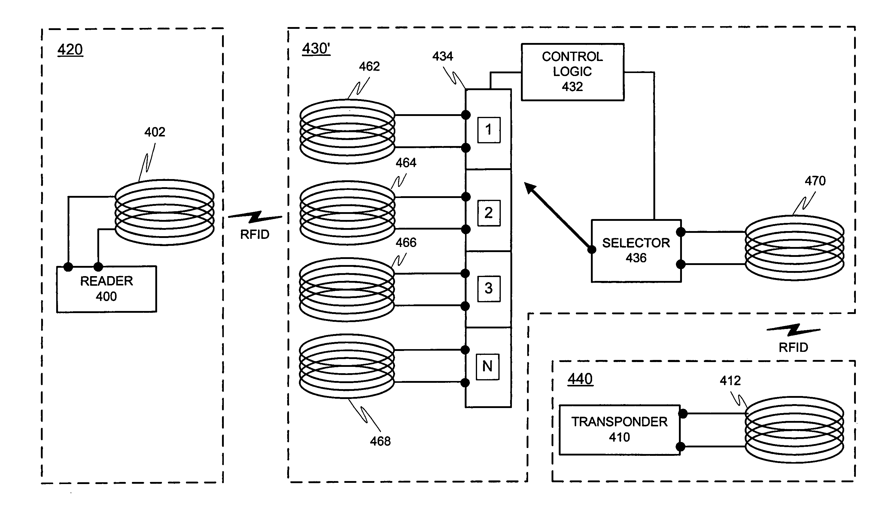
[0041] The present invention may be employed in enhancing or extending the communication ability of a short-range machine-readable tag. While RFID tags will be discussed throughout the specification, the same system may be applied to any short-range machine-readable communication technology employing similar communication characteristics.

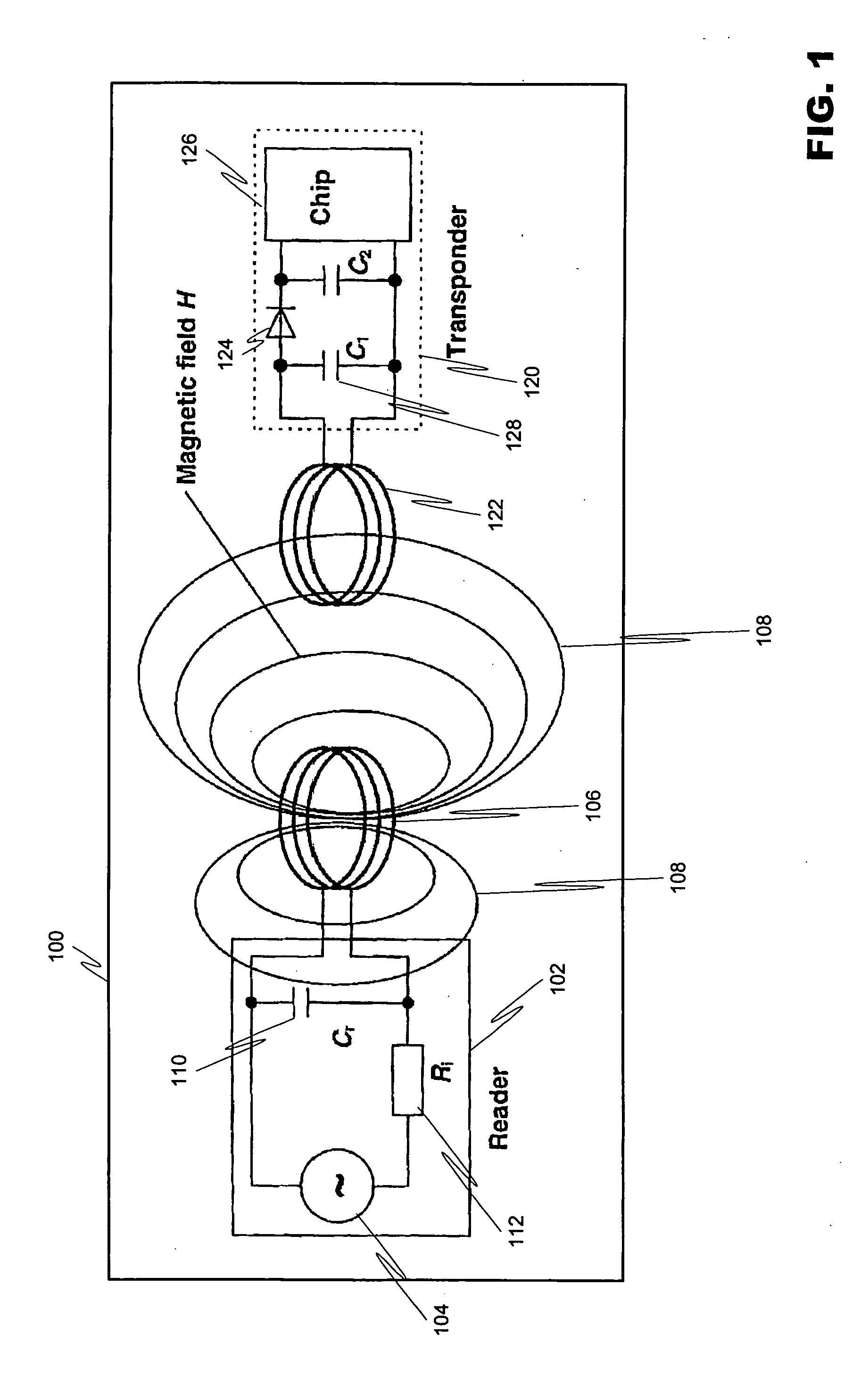
[0042]FIG. 1 depicts a baseline RFID reader / transponder system 100, which includes the reader 102 (also known as a scanner) and the transponder 120. The reader 102 includes an AC power source 104 connected to the reader's antenna coil 106, which generates a strong, high frequency electromagnetic field in the area around the reader's antenna coil 106. The strength of the field depends on the power source and the size and number of turns in the co...


PUM


Abstract

An intelligent antenna system for extending the effective communication range of a machine-readable passive tag. The system includes intelligence that allows one of a plurality of extension antennas to be active at any given time in order to both facilitate communications and safeguard the system. The machine-readable tag and antenna system may be embedded in a structure. In a further embodiment, the system may include multiple passive tags that are active in correspondence to a display or advertisement currently being exhibited. The system includes means for operatively coupling a designated machine-readable tag to the embedded antenna network previously described. In a further embodiment of the invention, the machine-readable tag includes combined RFID and NFC functionality where both RFID listening functions and NFC read-write functions are to be available in the same NFC communications logic, where different RFID listening applications require different minimum separation distances between the reader and the NFC communications logic. The NFC communications logic chip is selectively connected to at least three antenna coils, the first antenna coil for operating with a first minimum separation distance between the reader and the NFC communications logic, the second antenna coil for operating with a second minimum separation distance between the reader and the NFC communications logic, and the third antenna coil for reading and writing. In a further embodiment of the invention, matching circuits are included with the respective antenna coils to tune the resonant frequency of the RLC oscillator circuit for each antenna coil in the NFC communications logic.

Description

[0001] This application is a continuation-in-part of application Ser. No. 11 / 151,310, filed Jun. 14, 2005, presently pending before the United States Patent and Trademark Office and assigned to the same assignee, to which priority under 35 § USC 120 is claimed.BACKGROUND OF INVENTION [0002] 1. Field of Invention [0003] The present invention relates to wireless communications. More particularly, the invention is related to a system for improving the transmission of information via short-range communication through an improved multiple antenna arrangement for expanding the otherwise limited operational coverage area of a short-range communication source. [0004] 2. Description of Prior Art [0005] A wireless communication device (WCD) may communicate over a multitude of networks. Cellular networks facilitate WCD communications over large geographic areas. For example, the Global System for Mobile Telecommunications (GSM) is a widely employed cellular network that communicates in the 900...

Claims


Application Information

Patent Timeline
IPC IPC(8): G08B13/14
CPCG06K7/0008G06K7/10316G06K7/10237G06K7/10178H04B5/00H04B7/00
Inventor SAARISALO, MIKKOVITTANIEMI, PEKKA K.
Owner III HLDG 3
Why Eureka
Try Eureka