

Image data processing apparatus and image data processing method
- Summary
- Abstract
- Description
- Claims
- Application Information
AI Technical Summary
Benefits of technology
Problems solved by technology
Method used
Image

Examples
first embodiment
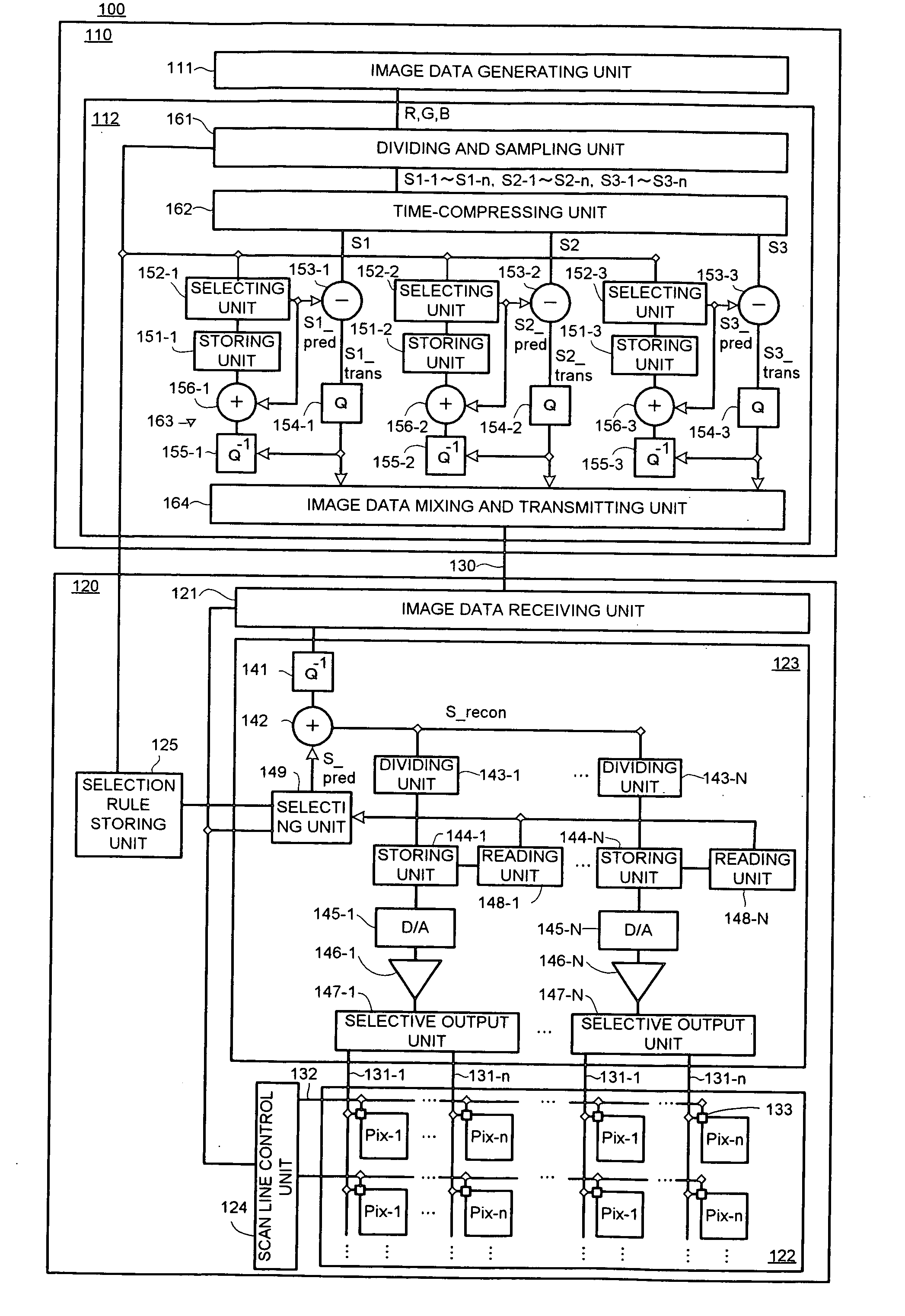
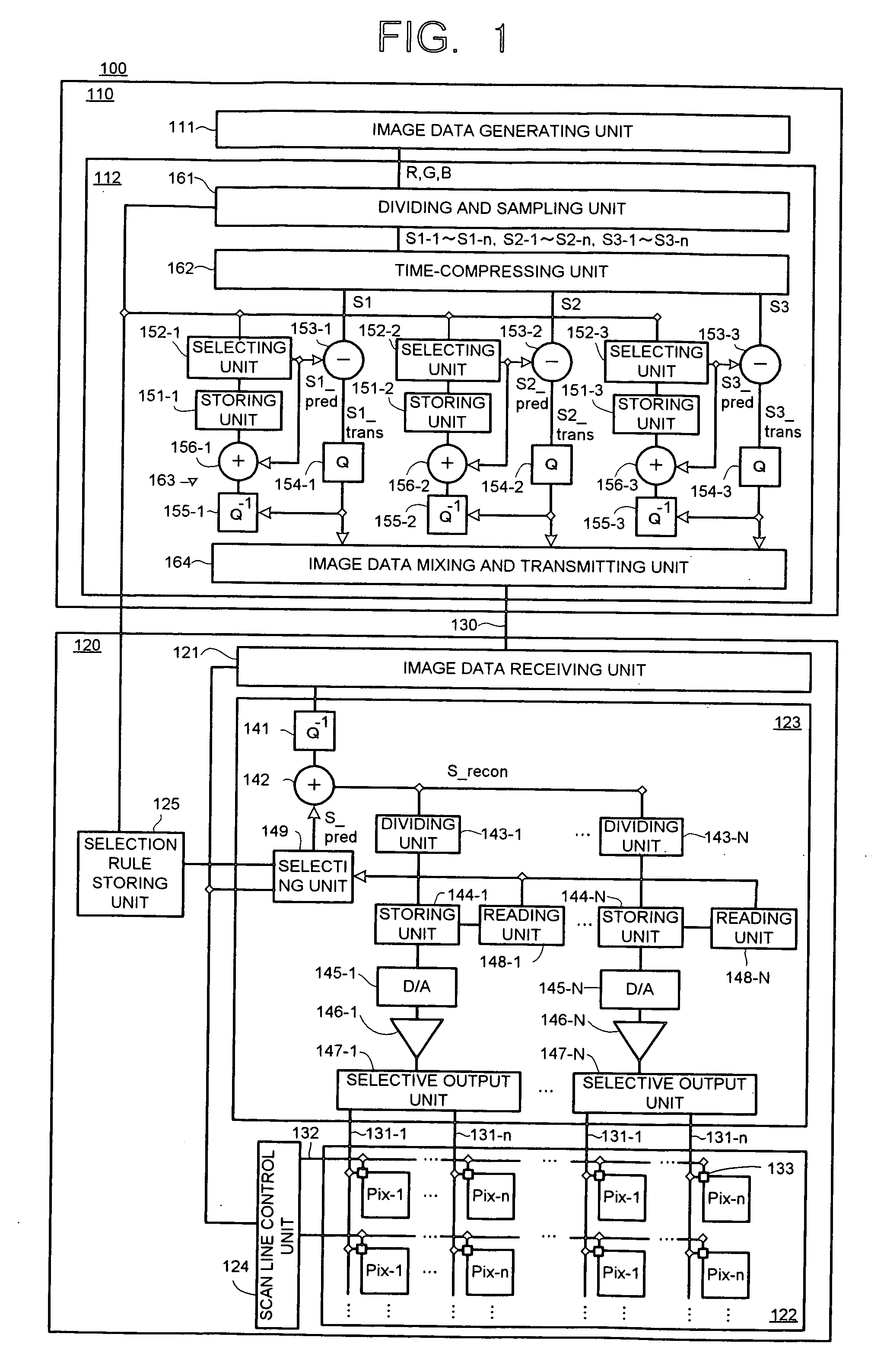
[0061]FIG. 1 is a block diagram representing a display system 100 according to a first embodiment of the present invention. The display system 100 has an image data transmitting device 110, an image data receiving device 120, and signal lines 131.
[0062] The image data transmitting device 110 is, for example, a computer, a television tuner, or the like which generates and transmits a differential signal for driving a display panel 122, and has an image data generating unit 111 and a differential data transmitting unit 112.
[0063] The image data receiving device 120 is, for example, a display module such as a liquid crystal display device which receives the differential signal from the image data transmitting device 110 and displays an image, and has an image data receiving unit 121, a display panel 122, a signal line control unit 123, a scan line control unit 124, and a selection rule storing unit 125.
[0064] The image data generating unit 111 generates and outputs image data for di...
modification example
of the First Embodiment
[0177]FIG. 26 is a block diagram representing a display system 100a according to a modification example of the first embodiment of the present invention.
[0178] In this modification example, differential data are not quantized when being transmitted. Accordingly, a differential data generating unit 163a does not have the quantizing units 154 in the first embodiment, and furthermore, it does not have the storing units 151, the selecting units 152, the dequantizing units 155, and the adding units 156. In other words, configurations regarding the quantization itself and the accumulation of quantization errors are excluded, and instead of them, selecting and storing units 152a are arranged and the predicted values S_pred are selected from the output itself from a time-compressing unit 162.
[0179] Also, in a signal line control unit 123a, the dequantizing unit 141 in the first embodiment is excluded.
[0180] Except the above points, this modification example is not ...
second embodiment
[0181]FIG. 27 is a block diagram representing a display system 200 according to a second embodiment of the present invention.
[0182] In this embodiment, selection rules are determined on an image data transmitting device 210 side and transmitted with differential data to an image data receiving device 220. Accordingly, the image data transmitting device 210 has a differential accumulating unit 213 and a selection rule determining unit 214.
[0183] The differential accumulating unit 213 generates various differential data based on sampling pattern candidates and accumulates absolute values of differences of the respective sampling pattern candidates. The sampling pattern candidates are obtained from a pattern candidate storing unit 225 in the image data receiving device 220.
[0184] The selection rule determining unit 214 determines a sampling pattern and selection rules suitable for the sampling pattern, based on accumulation results in the differential accumulating unit 213.
(Operat...
PUM
 Abstract
Description
Claims
Application Information