Computer graphics rendering method and apparatus

a computer graphics and rendering method technology, applied in the field of computer graphics rendering methods and apparatuses, can solve problems such as non-uniform color gradations between, and achieve the effect of accurate overwriting

Inactive Publication Date: 2007-01-11
PANASONIC CORP
View PDF9 Cites 5 Cited by
  • Summary
  • Abstract
  • Description
  • Claims
  • Application Information

AI Technical Summary

Benefits of technology

[0017] It is an object of the present invention to provide a computer graphics rendering method and apparatus capable of performing the Z value calculation in the z-buffer method, the calculation of the color value between different shapes in a case where the colors of a plurality of shapes on the same plane are gradually changed for a stereoscopic effect, and the like, in such a manner that it is possible to render an object in a precise manner and in a realistic and readily understandable manner.
[0037] Thus, in the present invention, any shape is rendered with respect to a reference plane using a uniform set of parameters for the reference plane. For example, in a case where a hidden surface removal operation is performed by using the Z value based on the z-buffer method, the process specifies a plane as the reference plane, and calculates the Z value of a reference point on the reference plane, the gradient of the Z value in the X direction and that in the Y direction. Then, any shape is rendered by using the three Z value-related parameters obtained based on the reference plane. As a result, different coplanar shapes will have the same Z value at the same point. Therefore, it is possible to realize accurate overwriting.

Problems solved by technology

That is, in the conventional rendering method, the DDA method for a line segment and that for a quadrilateral are different rendering algorithms, and the Z value errors are caused by this difference between the rendering algorithms.
Not only does the difference between the rendering algorithms result in Z value errors when drawing one shape over another, but it also results in non-uniform color gradations between two coplanar shapes where the color of each shape is gradually changed for a stereoscopic effect.

Method used


Image

  • Computer graphics rendering method and apparatus
  • Computer graphics rendering method and apparatus
  • Computer graphics rendering method and apparatus

Examples


first embodiment

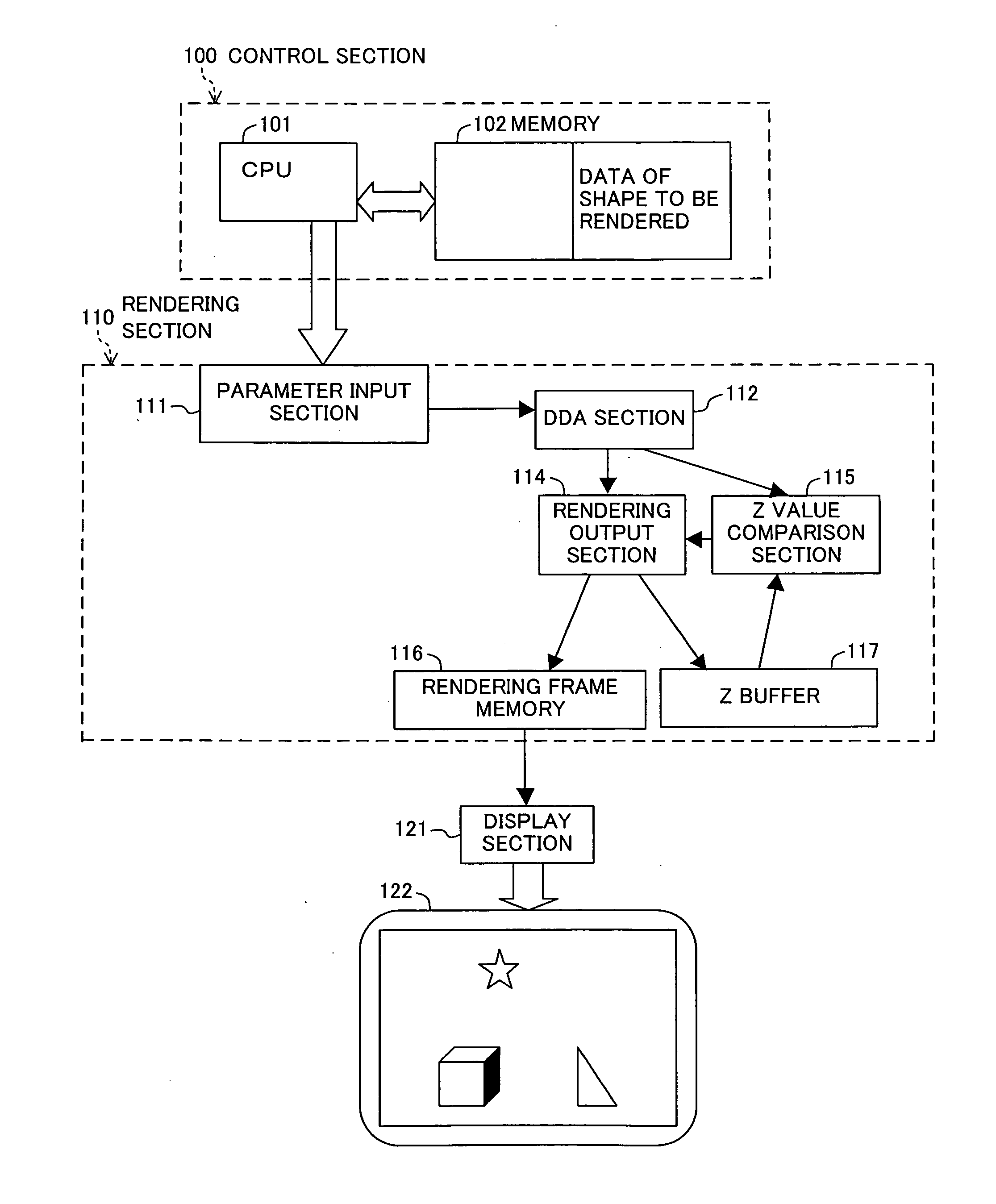
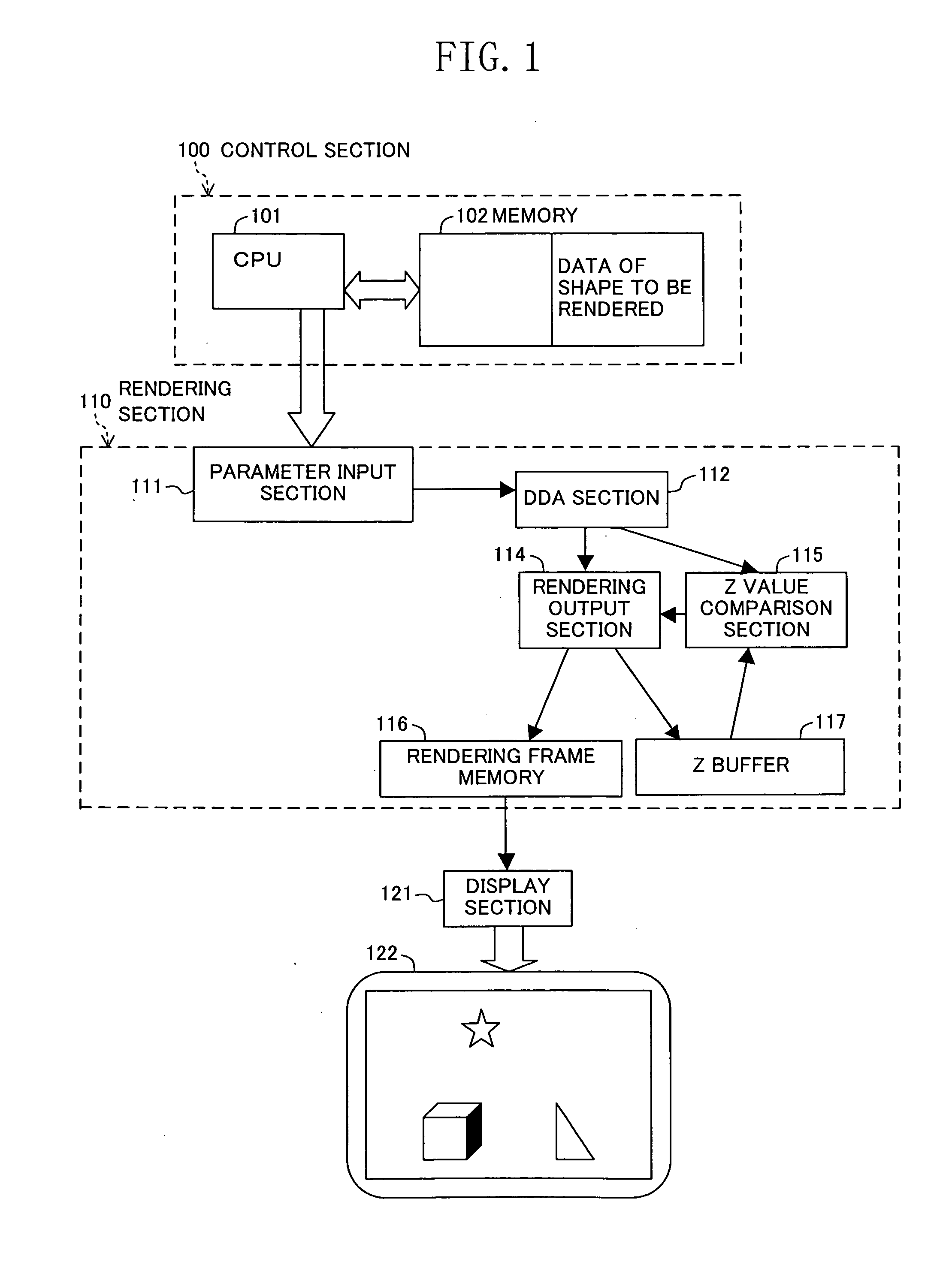
[0049]FIG. 1 shows a general configuration of a computer graphics rendering apparatus of the present invention.

[0050] Referring to data of shapes to be rendered stored in a memory 102, a CPU 101 of a control section 100 specifies a reference plane including the shapes based on the shape data, and calculates, as parameters, the Z value Zstart of a predetermined reference point on the specified reference plane, the amount dZdX by which the Z value changes for a +1 move in the X direction on the reference plane, and the amount dZdY by which the Z value changes for a +1 move in the Y direction. The calculated parameters are input to a parameter input section 111 of a rendering section 110.

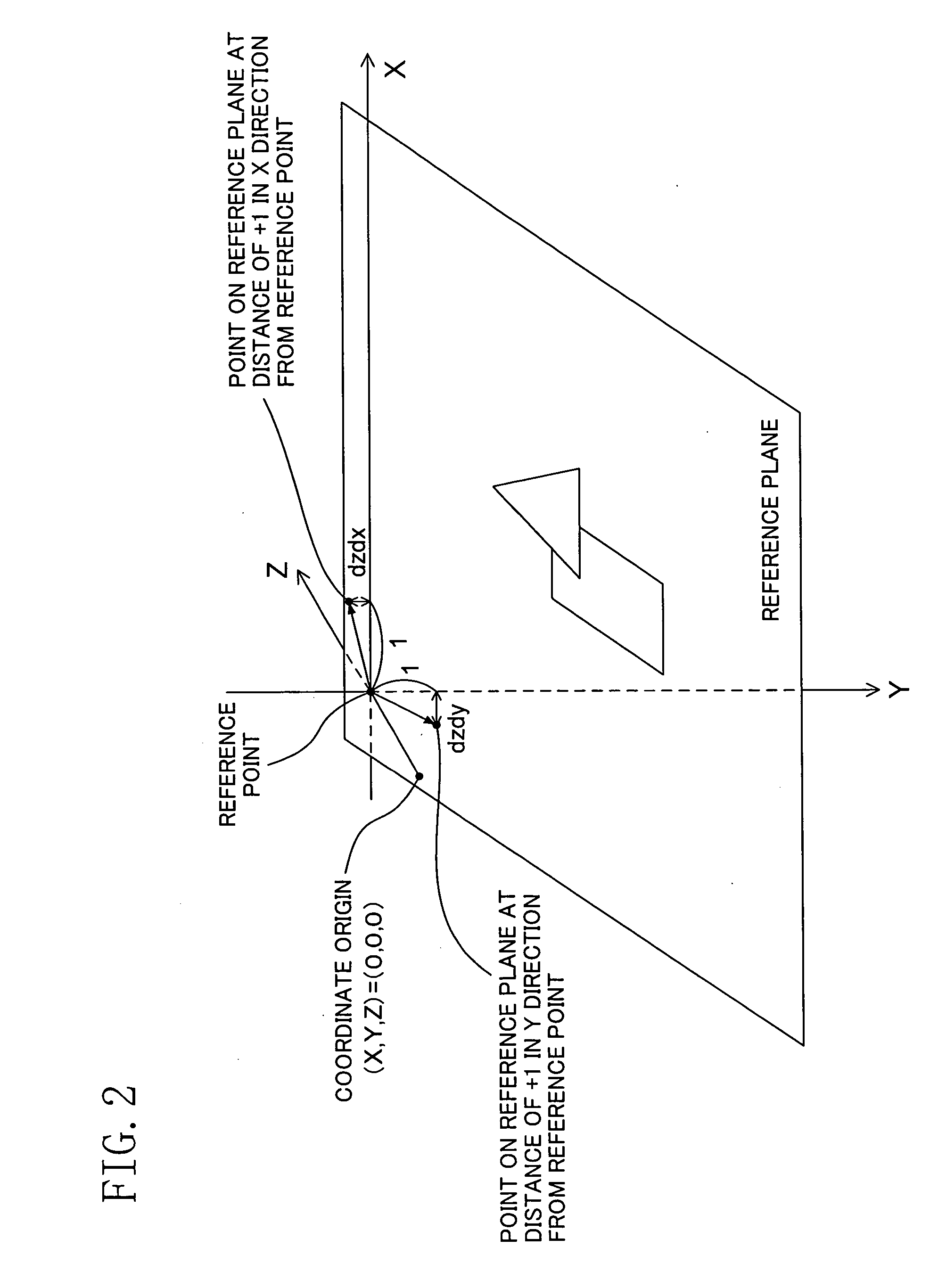
[0051] Where the point (X, Y)=(0, 0) is defined as the reference point on the reference plane, for example, the reference point is the intersection between the Z axis and the reference plane as shown in FIG. 2. The following description is based on this assumption.

[0052] The reference plane may be s...

second embodiment

[0075] A second embodiment of the present invention will now be described.

[0076] In the preceding embodiment, the Z value to be used for hidden surface removal when rendering a three-dimensional image is calculated based on the same algorithm irrespective of the type of a shape to be rendered. In the present embodiment, instead of the Z value as in the first embodiment, the transparency and the color of each point of a shape to be rendered are calculated based on the same algorithm irrespective of the type of a shape to be rendered, whereby there will be a uniform change in transparency and a uniform change in color among different shapes rendered, thus realizing a desirable stereoscopic effect.

[0077] In the present embodiment, instead of Zstart, dZdX and dZdY as in the first embodiment, the following values are first obtained: the transparency value αstart of a given reference point on a reference plane (it is assumed herein that the reference point is where (X, Y)=(0, 0)), the a...


PUM


Abstract

When a plurality of coplanar shapes are rendered over one another by performing a hidden surface removal operation using the Z value, a reference plane is specified, and the Z value of each point of a shape to be rendered on the reference plane is uniquely calculated based on the Z value of the rendering start point, the Z value gradient dZdx for the X direction, and the Z value gradient dZdy for the Y direction. Thus, any coplanar shapes will have the same Z value for each point shared therebetween. Therefore, if the rendering process is performed under such a rule that a shape is overwritten when the Z value of the new shape is less than or equal to the current Z value, it is ensured that the previously-rendered shape is always overwritten with a later-rendered, coplanar shape. Thus, it is possible to prevent a phenomenon that some pixels of a later-rendered shape that are supposed to be displayed are not displayed.

Description

CROSS REFERENCE TO RELATED APPLICATIONS [0001] This Non-provisional application claims priority under 35 U.S.C. §119(a) on Patent Application No. 2005-196560 filed in Japan on Jul. 5, 2005, the entire contents of which are hereby incorporated by reference. BACKGROUND OF THE INVENTION [0002] The present invention relates to a computer graphics rendering method and apparatus. [0003] Computer graphics rendering has been used widely in video games, car navigation systems, etc. In a video game, it is desirable that an object to be rendered, such as a human character, a car and a background object, is rendered beautifully in a realistic manner. In a car navigation system, it is desirable that an object to be rendered, such as a road, a building and a geographical feature, is rendered so that the rendered image is readily understood by the user. In order for the rendered image to be more realistic or more readily understandable, it is desirable that each object is rendered precisely at its...

Claims


Application Information

Patent Timeline
Patent Type & Authority Applications(United States)
IPC IPC(8): G06T15/40
CPCG06T15/405
Inventor MIDO, SHIGEAKISHIGENAGA, SATOSHI
Owner PANASONIC CORP
Why Eureka
Try Eureka