
Method of plasma etching transition metals and their compounds

a transition metal and plasma etching technology, applied in the field of plasma etching transition metals and their compounds, can solve the problems of difficult etching of compounds, and achieve the effect of efficient removal

Inactive Publication Date: 2007-01-11
SANDISK TECH LLC
View PDF0 Cites 62 Cited by
  • Summary
  • Abstract
  • Description
  • Claims
  • Application Information

AI Technical Summary

Benefits of technology

[0002] A method of plasma etching comprises using a primary etchant of carbon monoxide gas to etch a transition metal or a transition metal compound and form a volatile metal carbonyl by-product that can be efficiently removed during the plasma etch.

Problems solved by technology

Typically transition metals and transition metal compounds are difficult to etch since most common etchants produce non-volatile byproducts which remain on the etched surface, creating defects.

Method used


Image

  • Method of plasma etching transition metals and their compounds
  • Method of plasma etching transition metals and their compounds
  • Method of plasma etching transition metals and their compounds

Examples


Embodiment Construction

[0008] A method of plasma etching transition metals and transition metal compounds, including transition metal oxides, with carbon monoxide is disclosed. The following description is presented to enable any person skilled in the art to make and use the invention. For purposes of explanation, specific nomenclature is set forth to provide a thorough understanding of the present invention. Descriptions of specific applications and methods are provided only as examples. Various modifications to the preferred embodiments will be readily apparent to those skilled in the art, and the general principles defined herein may be applied to other embodiments and applications without departing from the spirit and scope of the invention. Thus, the present invention is not intended to be limited to the embodiments shown, but is to be accorded the widest scope consistent with the principles and steps disclosed herein.

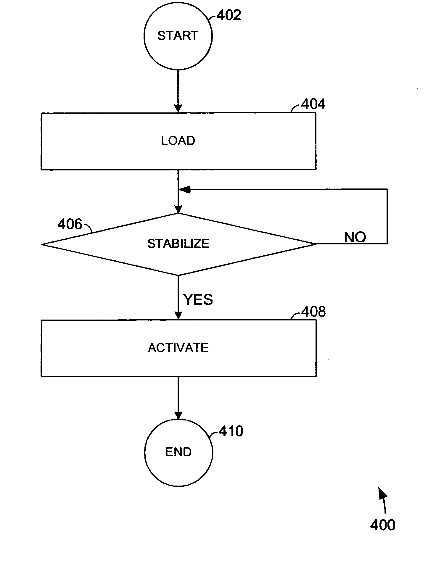
[0009] Referring now to the drawings and more particularly to FIG. 4 thereof, ther...


PUM

PropertyMeasurementUnit
Electrical conductoraaaaaaaaaa
Volatilityaaaaaaaaaa
aaaaaaaaaa

Abstract

A method of plasma etching comprises using a primary etchant of carbon monoxide gas to etch a transition metal or transition metal compound and to form a volatile by-product of metal carbonyl.

Description

BACKGROUND OF THE INVENTION 1. Background of Prior Art [0001] Typically transition metals and transition metal compounds are difficult to etch since most common etchants produce non-volatile byproducts which remain on the etched surface, creating defects. Therefore it would be highly desirable to have a new and improved method of plasma etching transition metal and transition metal compounds while simultaneously reducing defect levels significantly. BRIEF SUMMARY OF THE INVENTION [0002] A method of plasma etching comprises using a primary etchant of carbon monoxide gas to etch a transition metal or a transition metal compound and form a volatile metal carbonyl by-product that can be efficiently removed during the plasma etch.BRIEF DESCRIPTION OF THE DRAWINGS [0003] The above mentioned features and steps of the invention and the manner of attaining them will become apparent, and the invention itself will be best understood by reference to the following description of the preferred em...

Claims


Application Information

Patent Timeline
IPC IPC(8): H01L21/302
CPCC23F4/00H01L21/31122H01L21/32136H01L27/2409H01L45/1233H01L45/146H01L45/1675H01L45/04H10B63/20H10N70/20H10N70/826H10N70/8833H10N70/063
Inventor RAGHURAM, USHAKONEVECKI, MICHAEL
Owner SANDISK TECH LLC
Learn More