
Method for detection and diagnosis of isolation faults in fuel cell hybrid vehicles

a technology of fuel cell hybrid vehicles and isolation faults, which is applied in the direction of battery/fuel cell control arrangement, electric devices, instruments, etc., can solve the problems of causing short circuits, causing hazardous current flow through the human body, and affecting the operation of the vehicl

Active Publication Date: 2007-01-18
GM GLOBAL TECH OPERATIONS LLC
View PDF9 Cites 57 Cited by
  • Summary
  • Abstract
  • Description
  • Claims
  • Application Information

AI Technical Summary

Benefits of technology

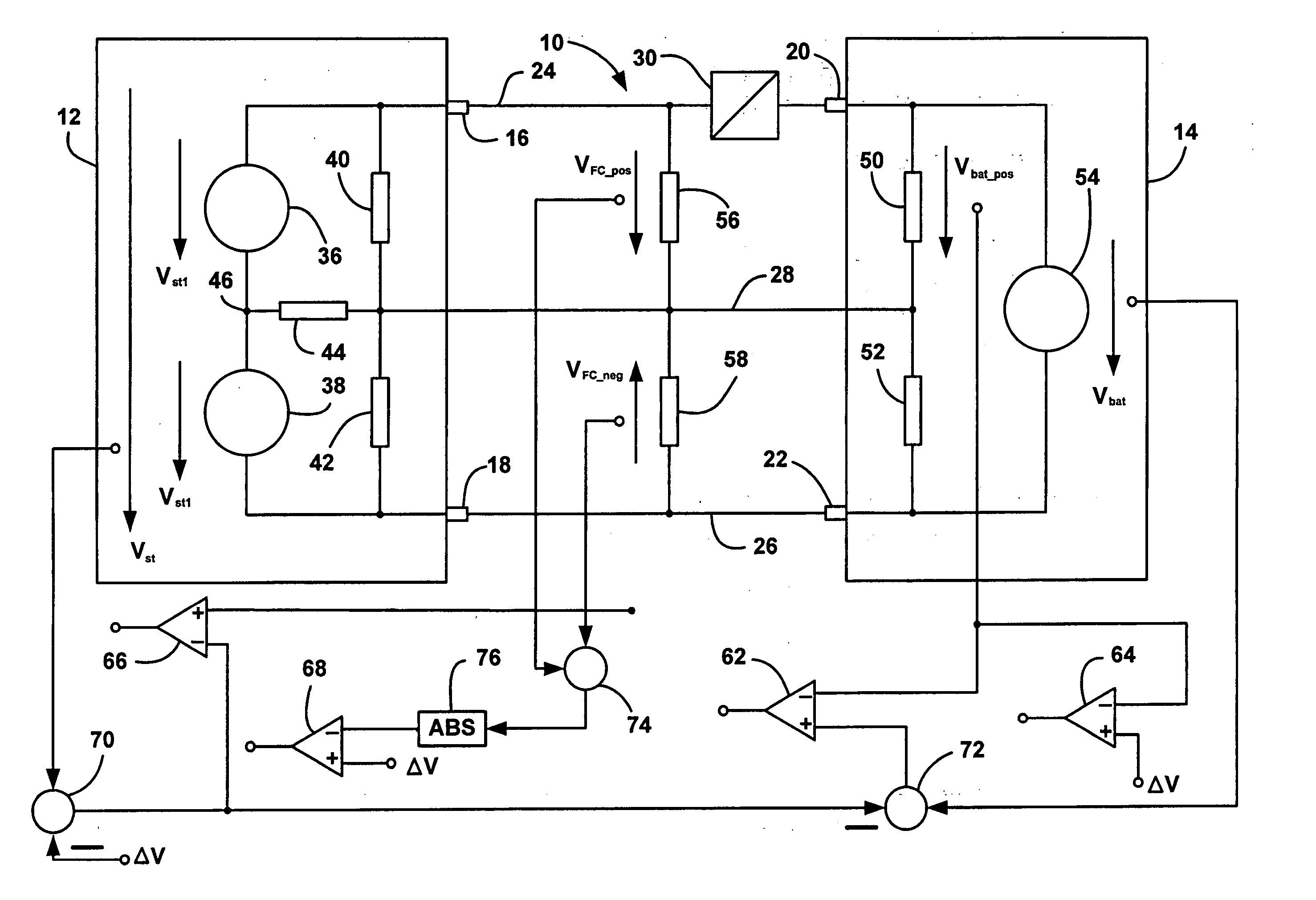
[0010] In accordance with the teachings of the present invention, an isolation fault detection system is disclosed for detecting isolation faults in a fuel cell system associated with a fuel cell hybrid vehicle. A plurality of isolation resistances are defined in the fuel cell system. The isolation fault detection system measures a stack voltage potential, a positive fuel cell voltage potential, a negative fuel cell voltage potential, a positive battery voltage potential, and an overall battery voltage potential. ...

Problems solved by technology

However, various operating conditions of the vehicle may cause a high voltage part of the electrical system to be directly coupled to the vehicle chassis during vehicle operation.
However, as time goes by, the cooling fluid becomes contaminated and more conductive, which could cause an impermissible current flow to the vehicle chassis.
In the worst case, a short circuit can occur.
In the case of a fault, accessible live parts of the power bus from, for example, damaged cable insulation, unplugged connectors, removed converter covers, etc., can create a hazardous current flow through a human body.
Conventional isolation fault detection devices cannot effectively be used in fuel cell hybrid vehicles because the isolation resistances in the fuel cell stack are asymmetrical.
Thus, conventional isolation fault detection systems that rely on an imbalance between voltage potentials to indicate the fault cannot be used in a fuel cell system.

Method used


Image

  • Method for detection and diagnosis of isolation faults in fuel cell hybrid vehicles
  • Method for detection and diagnosis of isolation faults in fuel cell hybrid vehicles

Examples


Embodiment Construction

[0013] The following discussion of the embodiments of the invention directed to an isolation fault detection system for a fuel cell system is merely exemplary in nature, and is in no way intended to limit the invention or its applications or uses. For example, the isolation fault detection system of the invention has particular application for a fuel cell hybrid vehicle. However, as will be appreciated by those skilled in the art, the isolation fault detection system of the invention may have use for other applications.

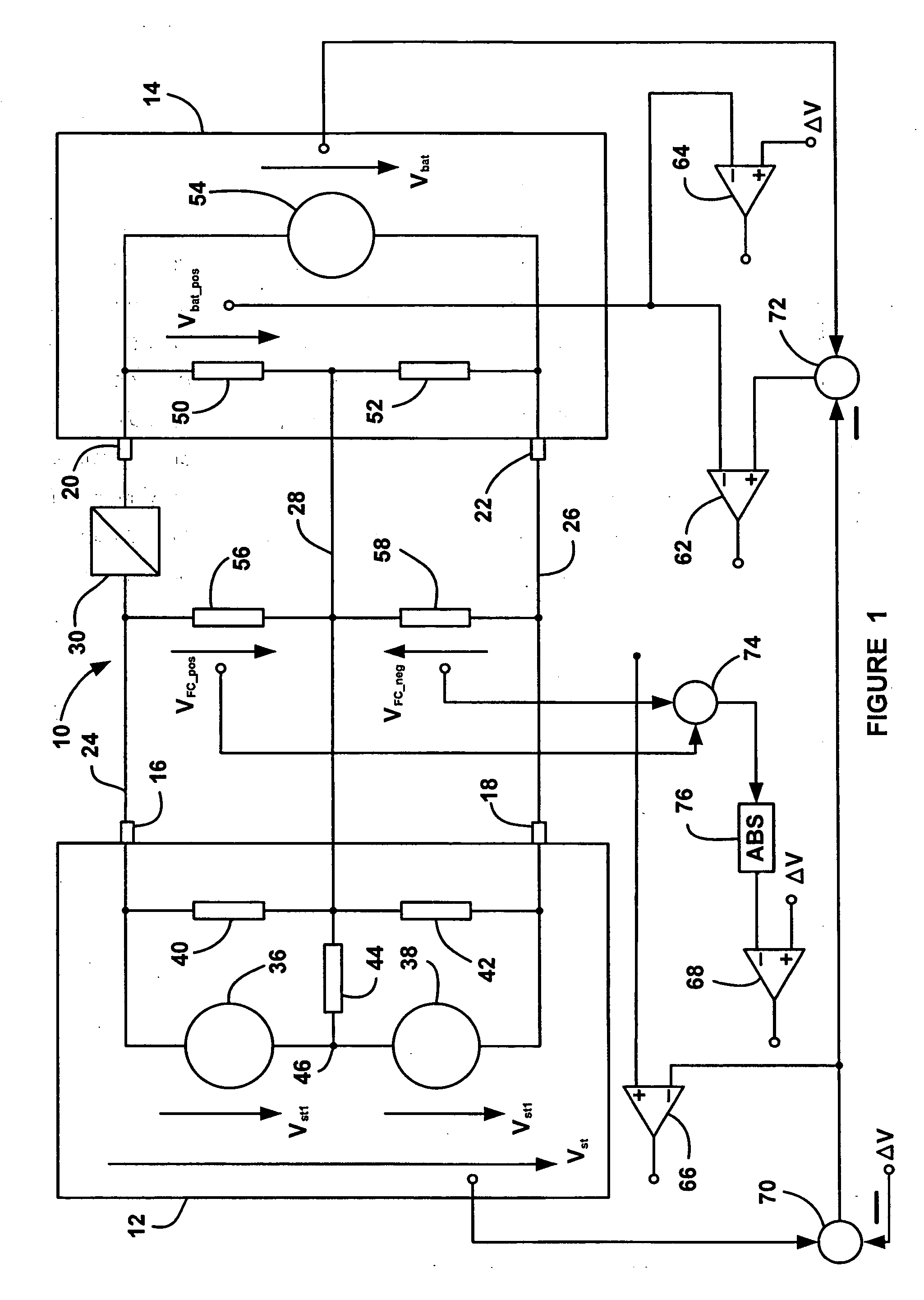
[0014]FIG. 1 is a schematic diagram of an isolation fault detection system 10 for a fuel cell system associated with a fuel cell hybrid vehicle. The system 10 includes an equivalent circuit of various electrical components of the fuel cell system. The system 10 includes a fuel cell stack 12 and a secondary battery 14. The fuel cell stack 12 includes a positive stack terminal 16 and a negative stack terminal 18, and the battery 14 includes a positive battery terminal ...


PUM


Abstract

An isolation fault detection system for detecting isolation faults in a fuel cell system associated with a fuel cell hybrid vehicle. The isolation fault detection system measures a stack voltage potential, a positive fuel cell voltage potential, a negative fuel cell voltage potential, a positive battery voltage potential, and an overall battery voltage potential. The isolation fault detection system then uses these voltage potentials in mesh equations to compare the measured voltage potentials to voltage potentials that would occur during a loss of isolation. In one embodiment, the isolation fault detection system uses these five measured voltage potentials to determine whether an isolation fault has occurred at four separate locations in the fuel cell hybrid vehicle. The system also can detect the location of the isolation fault.

Description

BACKGROUND OF THE INVENTION [0001] 1. Field of the Invention [0002] This invention relates generally to a system and method for providing high voltage isolation fault detection in a fuel cell hybrid vehicle and, more particularly, to an isolation fault detection system for providing high voltage isolation fault detection in a fuel cell hybrid vehicle, where various voltage potentials are measured and compared with voltage potentials that would occur during an isolation fault to detect the isolation fault. [0003] 2. Discussion of the Related Art [0004] Hydrogen is a very attractive fuel because it is clean and can be used to efficiently produce electricity in a fuel cell. The automotive industry expends significant resources in the development of hydrogen fuel cells as a source of power for vehicles. Such vehicles generate zero emissions and would be more efficient than today's vehicles employing internal combustion engines. [0005] A hydrogen fuel cell is an electrochemical device th...

Claims


Application Information

Patent Timeline
IPC IPC(8): G01R31/00H01M16/00
CPCB60L3/0046Y02T90/34B60L11/1881B60L11/1892B60L11/1894G01R31/12G01R31/36H01M8/04246H01M8/04552H01M8/04559H01M8/04567H01M8/04671H01M8/04679H01M8/04686H01M16/003Y02E60/50B60L3/0053B60L58/30B60L58/33B60L58/34B60L58/40Y02T90/40Y02T10/70
Inventor HINZ, HARTMUTDOENITZ, STEFFEN
Owner GM GLOBAL TECH OPERATIONS LLC
Learn More