Liquid crystal panel and liquid crystal display using the same

a liquid crystal display and liquid crystal panel technology, applied in non-linear optics, instruments, optics, etc., can solve the problems of difficult to achieve perfect black display, light leakage, light leakage, etc., and achieve wide wavelength range, suppress color shifting, and high contrast ratio

Inactive Publication Date: 2007-01-18
NITTO DENKO CORP
View PDF11 Cites 6 Cited by
  • Summary
  • Abstract
  • Description
  • Claims
  • Application Information

AI Technical Summary

Benefits of technology

[0009] The present invention was made with the foregoing in mind, and it is an object of the present invention to provide a VA-mode liquid crystal panel that has a high contrast ratio over a wide wavelength range and a suppressed color shifting.

Problems solved by technology

However, the TN mode has driving characteristics in which liquid crystal molecules in the vicinity of the substrates generate birefringence even when attempting a black display, resulting in light leakage, making it difficult to achieve a perfect black display.
However, although a substantially perfect black display can be achieved in a direction normal to the panel in the VA mode, the influence of the birefringence of the liquid crystal becomes apparent when the panel is observed from a direction deviated from the normal direction (an oblique direction), leading to light leakage.
As a result, the VA mode has had a problem that a viewing angle is small.
However, even if the birefringence of the liquid crystal layer is compensated for, the light leakage due to the polarizing plates occurs in the directions deviated from an optical axis of the polarizing plates, causing a problem of lowering contrast.
This is basically because, even if a crossed Nicols state is achieved with polarizers obtained by allowing a PVA-based film to adsorb a dichroic material such as iodine, light leakage occurs inevitably as a visual angle is inclined from the normal direction in the direction deviated from the optical axis.
However, this method only improves the viewing angle characteristics in terms of contrast, in other words, it reduces a leakage amount with respect to light in the vicinity of 550 nm having the highest luminous factor but does not provide any solution for a color shifting.
However, similarly to the above, this is also insufficient in terms of color shifting.
However, this method is also insufficient in terms of color shifting.

Method used


Image

  • Liquid crystal panel and liquid crystal display using the same
  • Liquid crystal panel and liquid crystal display using the same
  • Liquid crystal panel and liquid crystal display using the same

Examples


example 1

[0154] First, a film of trade name “Pureace WR” manufactured by TEIJIN LIMITED was stretched uniaxially in a longitudinal direction at 230° C., thus obtaining a birefringent layer A (2) with Re=145 nm and nx>ny=nz.

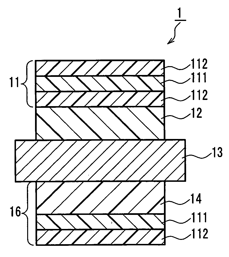
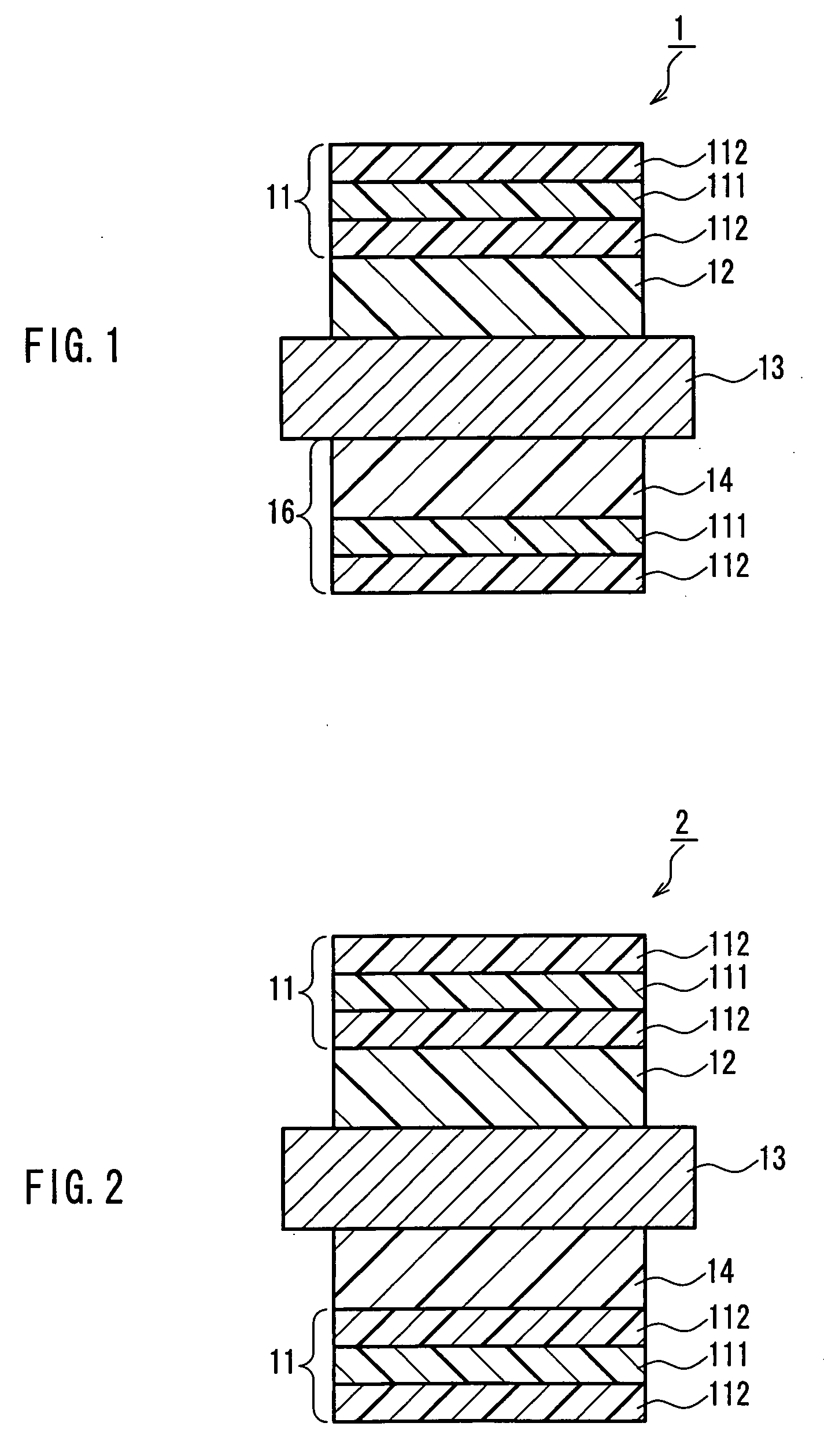
[0155] Using a pressure-sensitive adhesive, the polarizing plate of Comparative example 1 and the birefringent layer A (2) were attached to each other such that an absorption axis of the former and a slow axis of the latter were orthogonal to each other. On the other hand, an elliptical polarizing plate having the birefringent layer B (1) similarly to Comparative example 1 was used. Then, they were attached to the upper and lower surfaces of the liquid crystal cell C of Comparative example 1 via a pressure-sensitive adhesive such that the absorption axes of the two polarizers described above were orthogonal to each other, thus obtaining a liquid crystal panel (II). This liquid crystal panel had a configuration shown in FIG. 1.

example 2

[0156] First, a film of trade name “Pureace WR” manufactured by TEIJIN LIMITED was subjected to fixed-end transverse stretching at 230° C., thus obtaining a birefringent layer A (3) with Re=110 nm, Rth=160 nm and nx>ny>nz.

[0157] Polyimide synthesized by 2,2′-bis(3,4-dicarboxyphenyl)hexafluoropropane) and 2,2′-bis(trifluoromethyl)-4,4′-diaminobiphenyl) TFMB was dissolved in methyl isobutyl ketone and prepared to be 20 wt %. A PET film was coated with this solution and dried at 170° C. for 5 minutes. In this way, a birefringent layer B (3) with d=4.3 μm, Re=0.8 nm, Rth=172 nm, Δnxz=0.04 and nx=ny>nz was obtained.

[0158] The transparent protective layer of Comparative example 1 was attached to one side of the polarizer via an adhesive, while the birefringent layer A (3) was attached to the other side of the polarizer via an adhesive such that a slow axis of the former and an absorption axis of the latter were orthogonal to each other. Furthermore, the birefringent layer B (3) was tran...

example 3

[0160] First, a film of trade name “Pureace WR” manufactured by TEIJIN LIMITED was stretched uniaxially in a longitudinal direction at 230° C., thus obtaining a birefringent layer A (4) with Re=97 nm and nx>ny=nz.

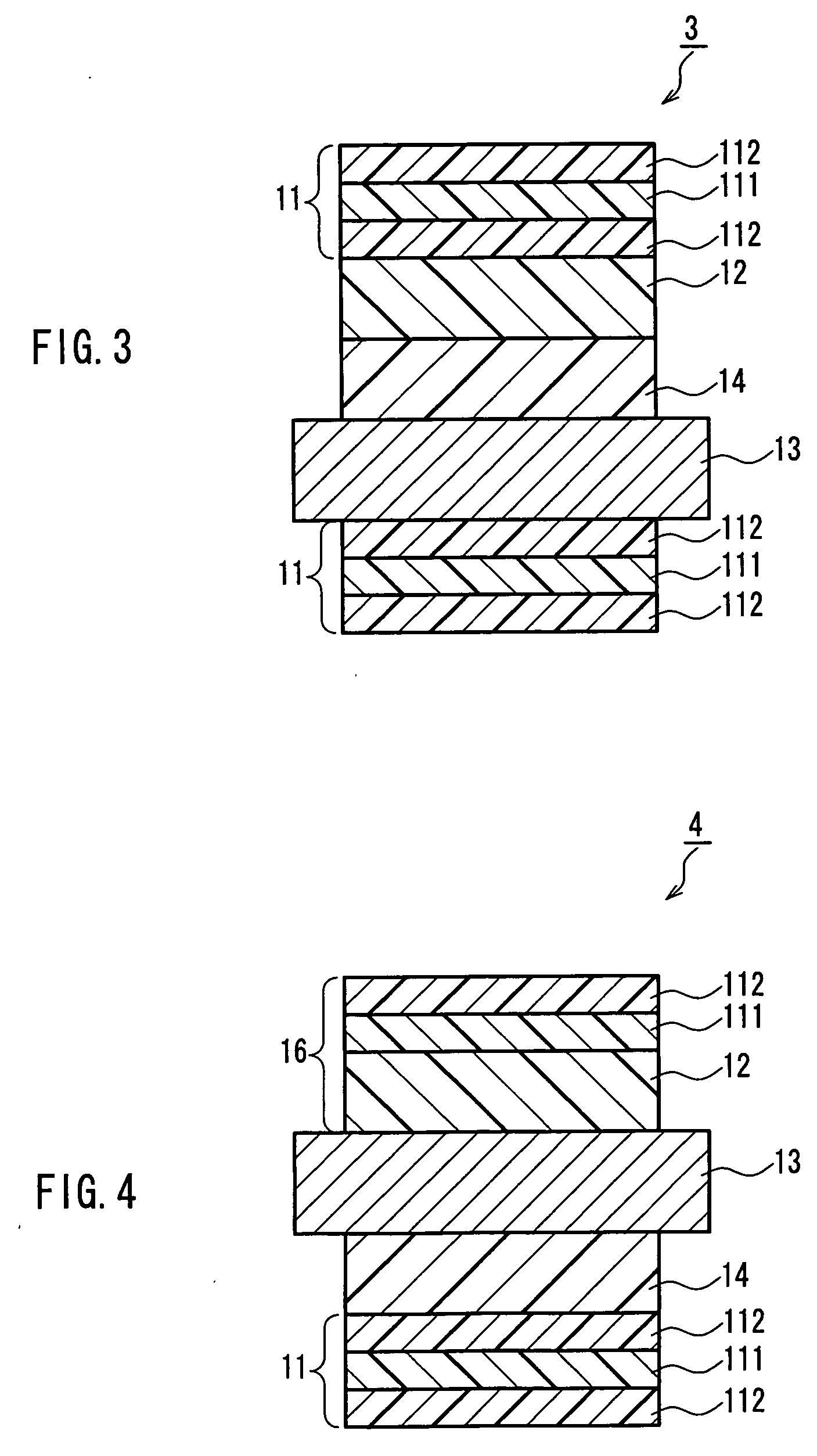
[0161] Polyimide synthesized by 2,2′-bis(3,4-dicarboxyphenyl)hexafluoropropane) and 2,2′-bis(trifluoromethyl)-4,4′-diaminobiphenyl) was dissolved in methyl isobutyl ketone and prepared to be 20 wt %. A TAC film was coated with this solution and dried at 130° C. for 5 minutes. Thereafter, the TAC film alone was subjected to fixed-end transverse stretching at 150° C., thus obtaining a birefringent layer B (4) with d=5.3 μm, Re=25 nm, Rth=235 nm, Δnxz=0.044 and nx>ny>nz. Using a pressure-sensitive adhesive, the polarizing plate of Comparative example 1 and the birefringent layer A (4) were attached to each other such that an absorption axis of the former and a slow axis of the latter were orthogonal to each other, and the other polarizing plate and the birefringent layer B (4...


PUM

PropertyMeasurementUnit
thicknessaaaaaaaaaa
incident angleaaaaaaaaaa

Abstract

A liquid crystal panel that has a high contrast ratio over a wide range and can suppress color shifting effectively is provided. In a liquid crystal panel including between two polarizing plates arranged in a crossed Nicols state a birefringent layer A with nx>ny≧nz, a birefringent layer B with nx≧ny>nz and a VA-mode liquid crystal cell C, it is set that a wavelength dispersion characteristic (α40(A)) of the birefringent layer A, a wavelength dispersion characteristic (α40(B)) of the birefringent layer B and a wavelength dispersion characteristic (α40(C)) of the liquid crystal cell C satisfy conditions α40(B)>α40(C)>α40(A) and 1>α40(A). The wavelength dispersion characteristic α40 represents a ratio of a retardation Re measured with incident light at 430 nm to that measured with incident light at 550 nm, the incident light being inclined by 40° with respect to a normal direction (0°) of a surface of the birefringent layer or a surface of the liquid crystal cell.

Description

BACKGROUND OF THE INVENTION [0001] 1. Field of the Invention [0002] The present invention relates to a liquid crystal panel and a liquid crystal display using the same. [0003] 2. Description of Related Art [0004] Conventionally, in liquid crystal displays, a so-called TN mode has been used primarily in which a liquid crystal having a positive dielectric constant anisotropy is horizontally aligned between substrates facing each other. However, the TN mode has driving characteristics in which liquid crystal molecules in the vicinity of the substrates generate birefringence even when attempting a black display, resulting in light leakage, making it difficult to achieve a perfect black display. On the other hand, there has been a VA mode in which liquid crystal molecules are aligned substantially vertically in a state where no voltage is applied. In the VA mode, since light passes through a liquid crystal layer while hardly changing its polarization plane, it is possible to achieve a su...

Claims


Application Information

Patent Timeline
Patent Type & Authority Applications(United States)
IPC IPC(8): G02F1/1335
CPCG02F1/133528G02F1/13363G02F1/133634G02F2413/02G02F2001/133742G02F2202/40G02F1/1393G02F1/133742
Inventor NISHIKOUJI, YUUICHIYOSHIMI, HIROYUKI
Owner NITTO DENKO CORP
Why Eureka
Try Eureka