Optical material, optical device fabricated therefrom, and method for fabricating the same

a technology of optical devices and optical materials, applied in the direction of polarizing elements, instruments, nanotechnology, etc., can solve the problems of inability to realize such a coating by which the reflection coefficient is achieved, the efficiency of such optics systems is extremely low, and the reflection loss yet to appear as to an s-polarization component remains

Inactive Publication Date: 2007-01-18
RIKEN
View PDF0 Cites 55 Cited by
  • Summary
  • Abstract
  • Description
  • Claims
  • Application Information

AI Technical Summary

Benefits of technology

[0028] Since the present invention is constructed as described above, there is such an excellent advantageous effect to provide an optical material which can make a reflection coefficient in the bounda

Problems solved by technology

Accordingly, there is such a problem that such Brewster phenomenon cannot be induced with respect to a light wave in s-polarization, so that reflection cannot be eliminated in the boundary surface except that either a particular surface treatment such as dielectric multilayer coating is applied, or a refractive index difference of a material is made to be zero.
Such a problem that a reflection loss yet appears as to an s-polarization component still remains.
Efficiency of such optics system decreases extremely, when a polarization direction of the incident lig

Method used


Image

  • Optical material, optical device fabricated therefrom, and method for fabricating the same
  • Optical material, optical device fabricated therefrom, and method for fabricating the same
  • Optical material, optical device fabricated therefrom, and method for fabricating the same

Examples


Embodiment Construction

[0045] In the following, an example of a manner of practice of the optical material according to the present invention, the optical device fabricated therefrom, and a method for fabricating the same will be described in detail by referring to the accompanying drawings.

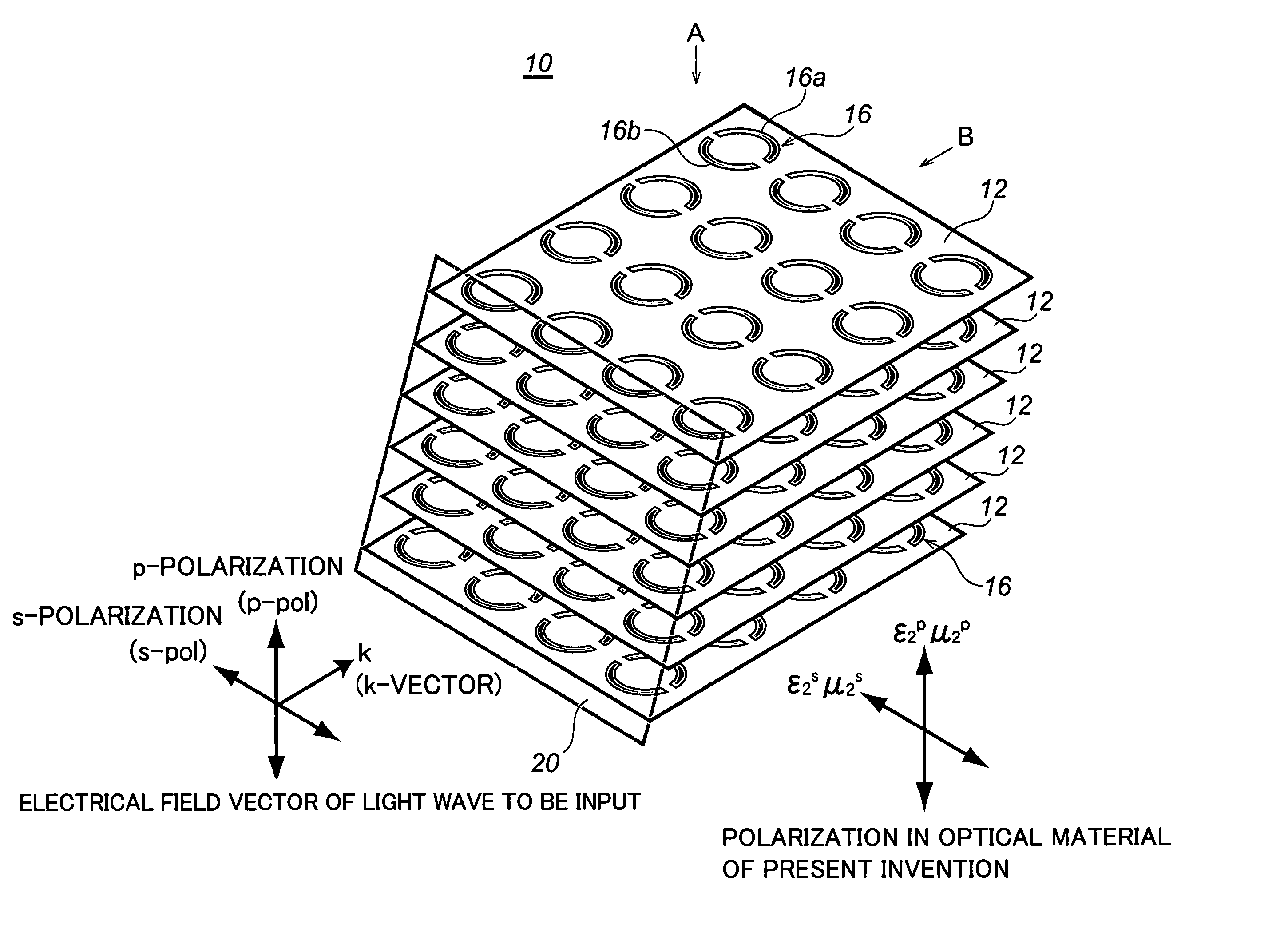
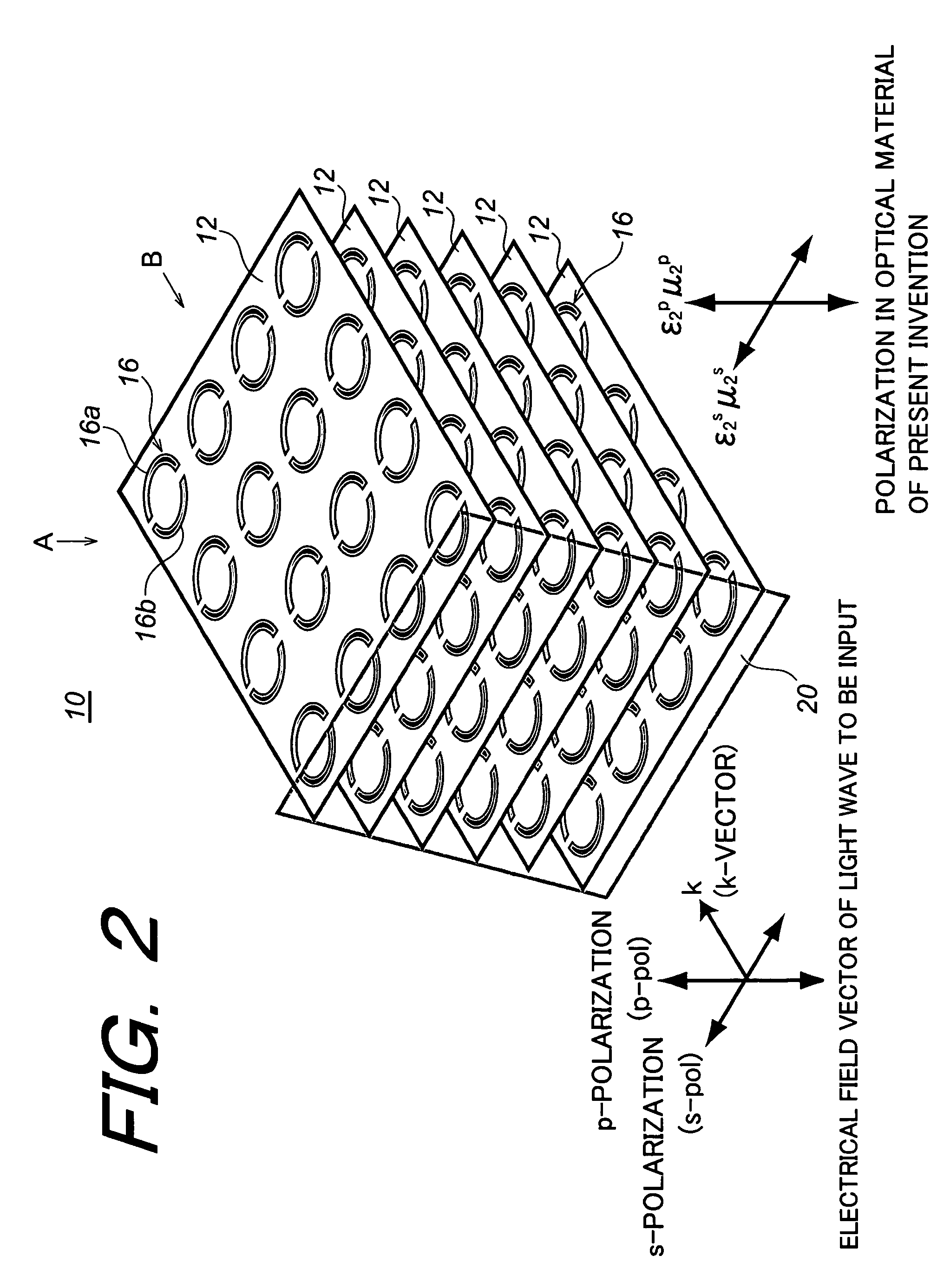
[0046] First, an optical material according to the present invention (hereinafter simply referred optionally to as “optical material of the invention” will be described. The optical material of the invention is composed of a metamaterial.

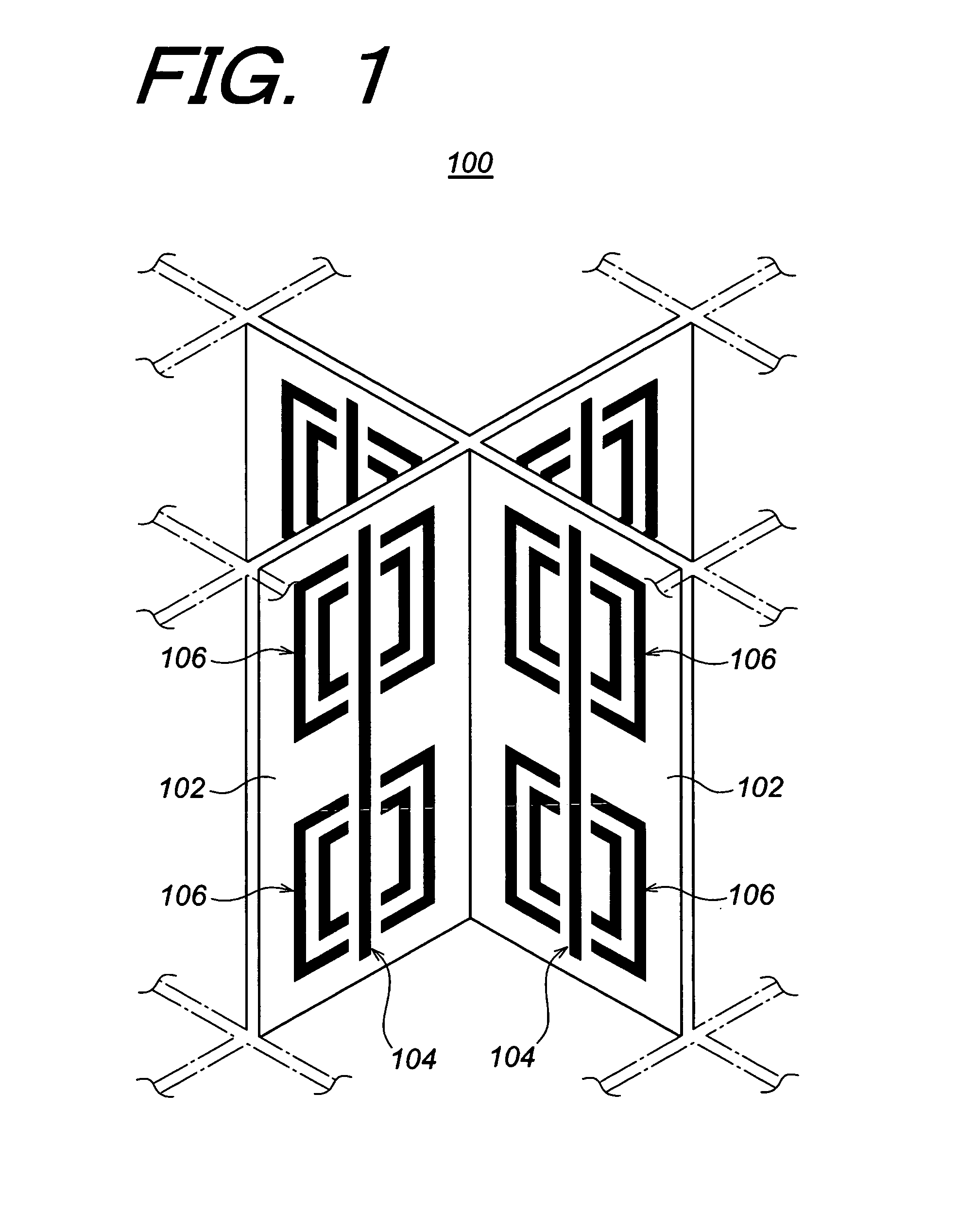
[0047] The metamaterial is constituted by three-dimensionally arranging dispersively micro-resonators each having a smaller wavelength than that of a light wave into a material, so that a resonation state of the micro-resonators which is smaller than a wavelength of the light wave to be input, whereby a dielectric constant or a magnetic permeability of such microscopic material are intended to be controlled.

[0048] The present invention has been made on the basis of the findings prov...


PUM


Abstract

In order to make a reflection coefficient in boundary surface between materials to be zero and permeate 100% of a light independent of a polarization direction, an optical device made of an optical material composed of a metamaterial prepared by arranging a plurality of at least either of electrical resonators or magnetic resonators each being smaller than a wavelength of a light wave in only a predetermined plane, and at least either of the electrical resonators and the magnetic resonators arranged functioning with respect to s-polarization, whereby at least either of the dielectric constant or the magnetic permeability is controlled in response to the function to induce a Brewster phenomenon in the s-polarization wherein the incident plane of a light wave being set out at a Brewster's angle with respect to the p-polarization and further at least either of the dielectric constant and the magnetic permeability of the optical material being controlled with respect to the s-polarization of the optical material, whereby the Brewster condition is independently satisfied in both the p-polarization and the s-polarization at the same time.

Description

BACKGROUND OF THE INVENTION [0001] 1. Field of the Invention [0002] The present invention relates to an optical material, an optical device fabricated therefrom, and a method for fabricating the same, and more particularly to an optical material, an optical device fabricated therefrom, and a method for fabricating the same utilizing a metamaterial [0003] 2. Description of the Related Art [0004] It is known that when a light wave inputs into a boundary surface between materials having different refractive indices from one another, reflection of the light appears in the boundary surface as an optical phenomenon. [0005] There are a variety of manners for interpretation as to the optical phenomenon. One of these interpretations is in that since a difference in refractive indices between materials functions as a potential barrier for a light wave, a part of the light wave is reflected. Another interpretation is in that when there is impedance mismatching in an electric circuit, electric ...

Claims


Application Information

Patent Timeline
IPC IPC(8): G02B27/28
CPCB82Y20/00G02F2202/30G02F1/0136G02B5/3066Y10S977/834
Inventor TANAKA, TAKUOKAWATA, SATOSHI
Owner RIKEN
Why Eureka
Try Eureka