Bicycle light assembly with auxiliary output connector

a technology of auxiliary output connector and bicycle light assembly, which is applied in the direction of bicycle equipment, lighting and heating apparatus, optical signal, etc., can solve the problems of limited amount of electrical components that a rider may use on his bicycle, inconvenience of periodic replacement, and use of batteries, so as to achieve efficient and space-saving effects

Inactive Publication Date: 2007-01-18
SHIMANO INC
View PDF3 Cites 60 Cited by
  • Summary
  • Abstract
  • Description
  • Claims
  • Application Information

AI Technical Summary

Benefits of technology

[0010] The present invention has been conceived to overcome these disadvantages in the prior art. Thus, one object of the present invention is to provide a bicycle light assembly that is configured to achieve the possibility of coupling a pl...

Problems solved by technology

While it is possible for each of the number of the above-mentioned electrical components to use batteries, the disadvantage of using batteries is to be seen in the inconvenience to replace them periodically.
Actually the amount of electrical components that a rider may use on his bicycle is limited.
Since a dynamo is designed to generate electricity th...

Method used


Image

  • Bicycle light assembly with auxiliary output connector
  • Bicycle light assembly with auxiliary output connector
  • Bicycle light assembly with auxiliary output connector

Examples


second embodiment

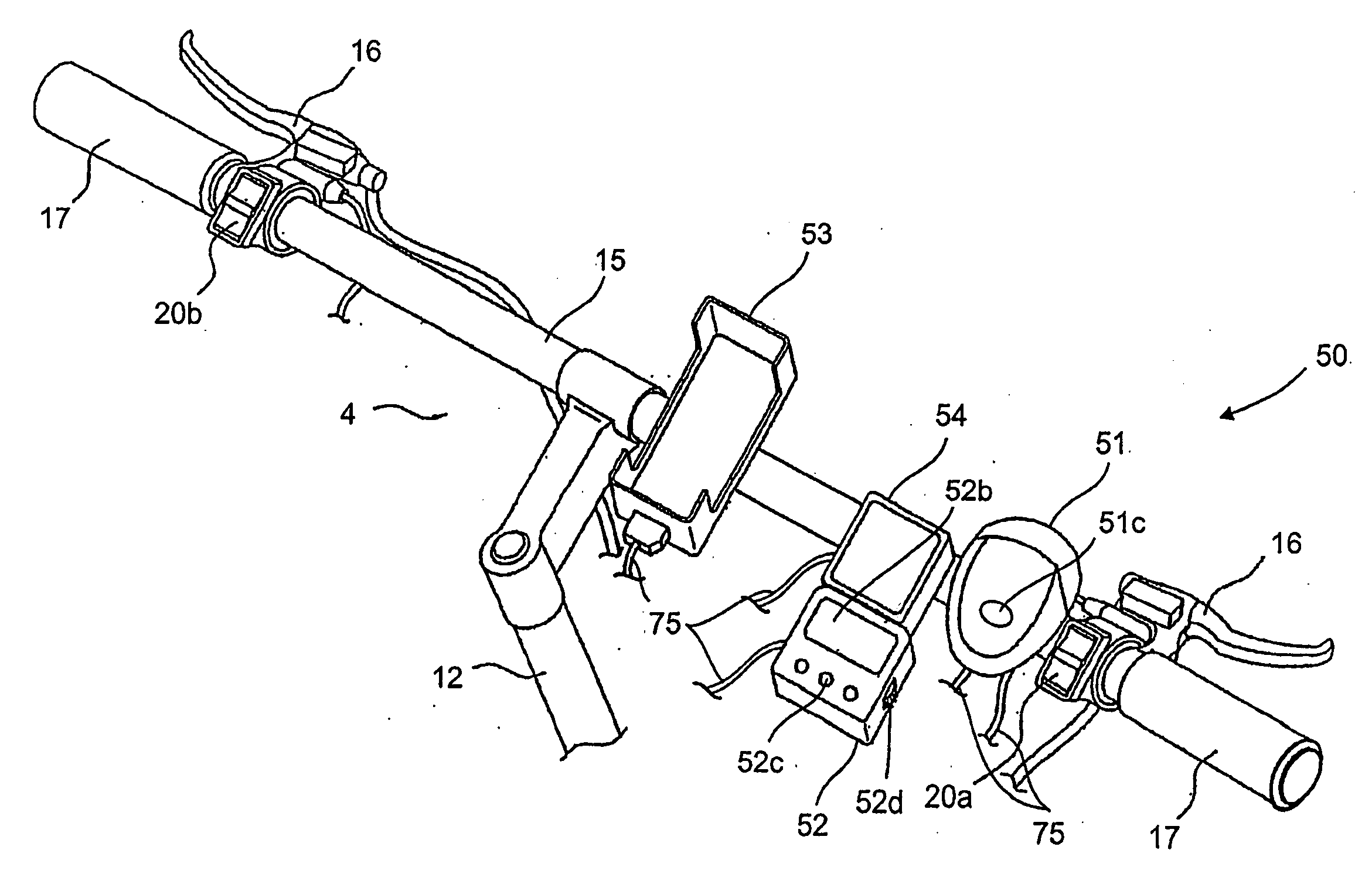
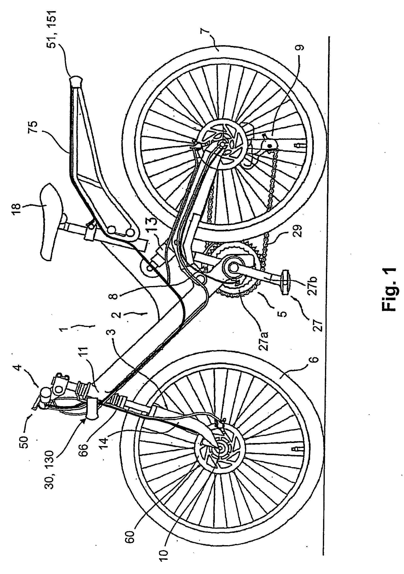
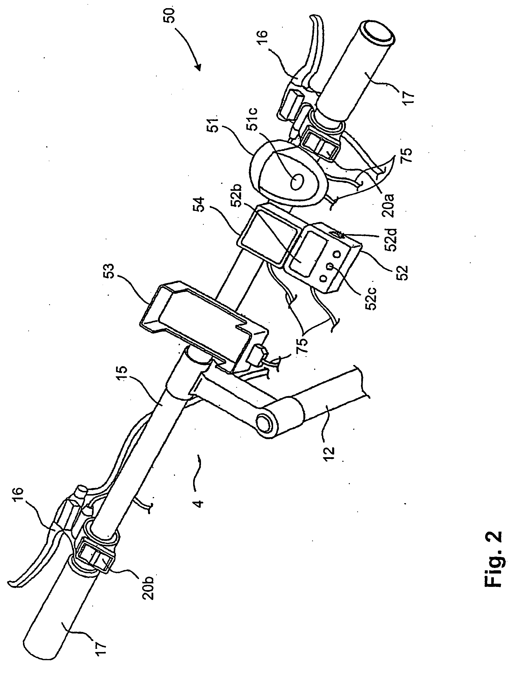
[0039] Referring now to FIG. 4, an alternate light assembly 130 is illustrated in accordance with a second embodiment. In view of the similarity between the first and second embodiments, the descriptions of the parts of the second embodiment that are identical to the parts of the first embodiment may be omitted for the sake of brevity. Moreover, identical parts will be given the same reference number. Basically, the light assembly 130 is installed on the bicycle 1 in place of the light assembly 30. Thus, the light assembly 130 corresponds to the light assembly 30, as shown in FIG. 3, except that a wave shape circuit 144 and a control unit 145 have been added, which are disposed inside the lamp housing 31 and connected to the input portion 32. In particular, the control unit 145 is disposed in the lamp housing 31 and connected to the wave shape circuit 144 and the regulator circuit 42.

[0040] The light assembly 130 is a component for supplying outputs, such as power or electrical sig...


PUM


Abstract

A bicycle light assembly is electrically connected to a dynamo. The bicycle light assembly has a lamp housing mountable to a portion of the bicycle. An input portion is disposed on the lamp housing and electrically connected to the dynamo for inputting a dynamo output signal and for outputting an input signal. A regulator circuit is electrically connected to the input portion for regulating the input signal to a regulated signal. A light source is electrically connected to the regulator circuit for lighting the periphery and an output portion being disposed on the lamp housing and electrically connected to the regulator circuit for outputting the regulated signal. The output portion has at least one auxiliary electrical output connector for outputting the regulated signal to at least one auxiliary electrical device electrically connected to the at least one auxiliary electrical output connector.

Description

CROSS-REFERENCE TO RELATED APPLICATIONS [0001] This application claims priority under 35 U.S.C. §119 to European Patent Application No. 05 015 070.5. The entire disclosure of European Patent Application No. 05 015 070.5 is hereby incorporated herein by reference. BACKGROUND OF THE INVENTION [0002] 1. Field of the Invention [0003] The present invention generally relates to a bicycle light assembly. More specifically, the present invention relates to a bicycle head light assembly electrically connected to a dynamo for supplying the output of the dynamo to at least one electrical component coupled to the light assembly. [0004] 2. Background Information [0005] Bicycling is becoming an increasingly more popular form of recreation as well as a means of transportation. Moreover, bicycling has become a very popular competitive sport for both amateurs and professionals. Whether the bicycle is used for recreation, transportation or competition, the bicycle industry is constantly improving the...

Claims


Application Information

Patent Timeline
IPC IPC(8): B62J6/00B62J11/19B62J99/00
CPCB62J6/001B62J6/18B62J6/02B62J6/01B62J6/029B62J11/19
Inventor KITAMURA, SATOSHI
Owner SHIMANO INC
Why Eureka
Try Eureka