Bone densitometry system for public use

a densitometry and public technology, applied in the field of bone densitometry systems for public use, can solve the problems of less familiarity and complexity of densitometry, and achieve the effect of costing the equipmen

Inactive Publication Date: 2007-01-18
GENERAL ELECTRIC CO
View PDF26 Cites 18 Cited by
  • Summary
  • Abstract
  • Description
  • Claims
  • Application Information

AI Technical Summary

Benefits of technology

[0007] The present inventor has recognized that large scale screening for severe osteoporosis might be possible using the model of “free” blood pressure checking kiosks found i...

Problems solved by technology

Generally, bone densitometers are far more complex and less familiar to the public than blood pressure machines, and ultrasonic ...

Method used


Image

  • Bone densitometry system for public use
  • Bone densitometry system for public use
  • Bone densitometry system for public use

Examples


Embodiment Construction

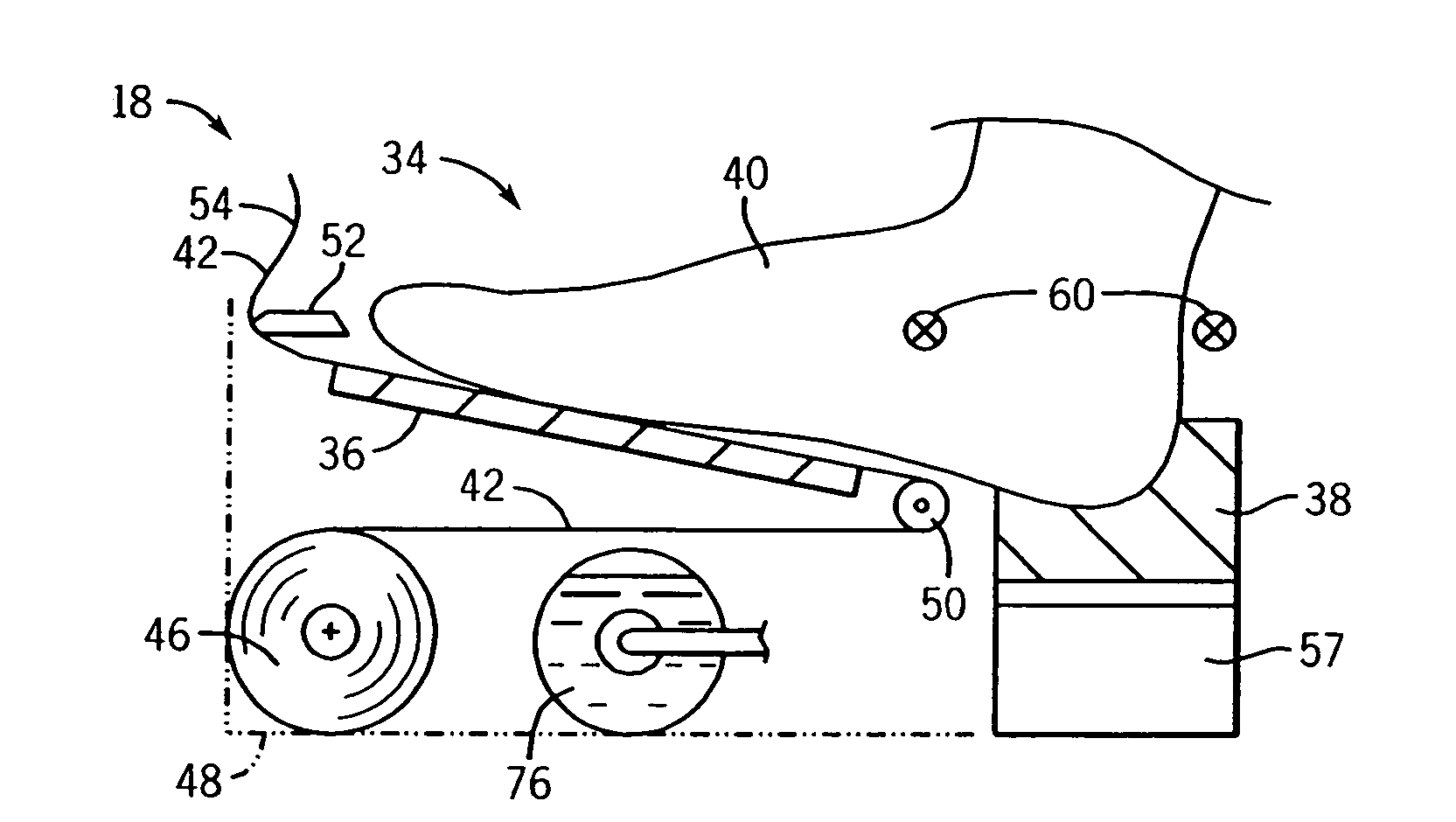
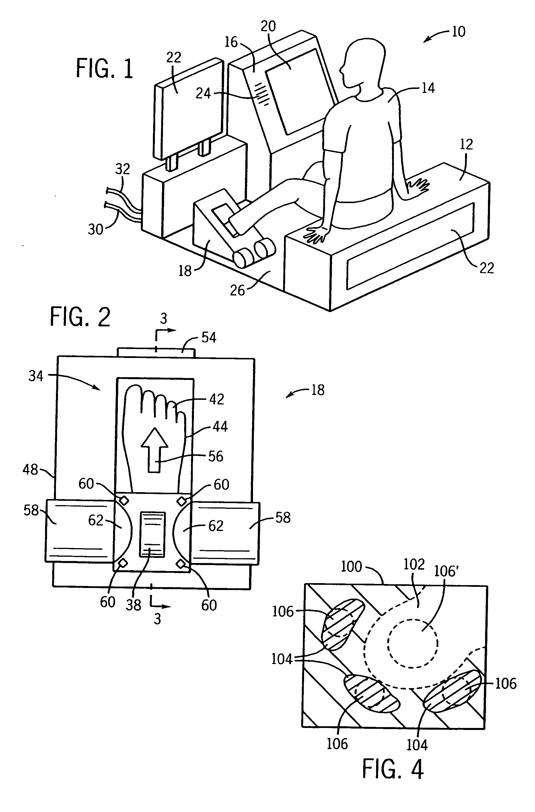
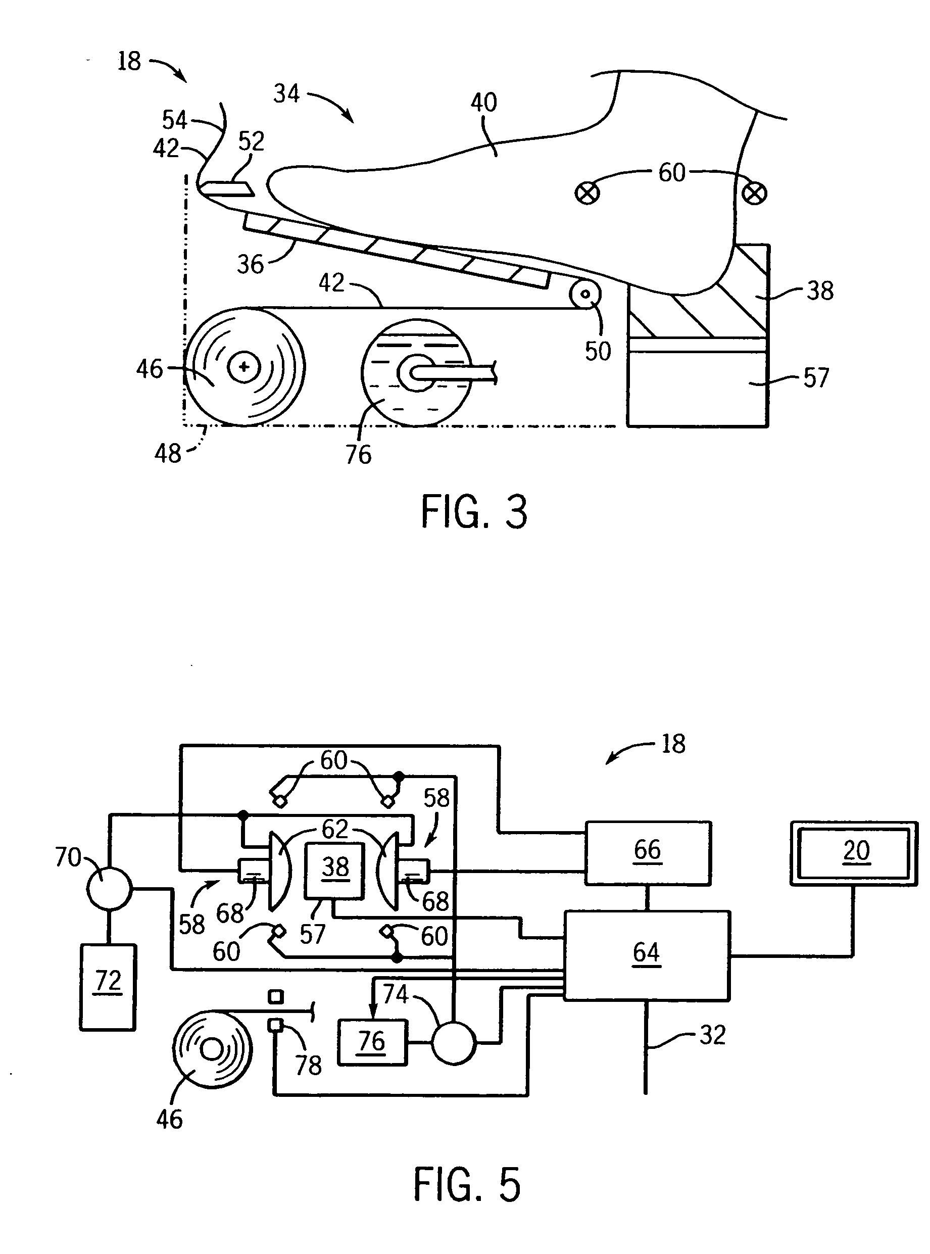
[0038] Referring now to FIG. 1, the present invention provides a bone densitometer kiosk 10. In the preferred embodiment, the kiosk 10 includes a bench 12 to support a patient 14 in a seated position, facing a display terminal 16, with one foot received by a floor unit 18.

[0039] The display terminal 16 provides a touch screen 20 allowing both display and data entry capabilities and is positioned to be easily viewed and operated by the patient 14 when seated upright on the bench 12 with her foot in the floor unit 18.

[0040] The kiosk 10 may include places for advertising placards 22 and advertising may also be periodically displayed on the touch screen 20 or on the bench 12.

[0041] The elements of bench 12, the display terminal 16, and floor unit 18 may be attached to a floor unit 26 or may be individually assembled in a store, mall or the like. Electrical connections 30 are provided for electrical power to power the kiosk 10 and optionally an Internet connection 32 that may be used...


PUM


Abstract

An ultrasonic bone densitometer system is provided in a kiosk environment using computer driven patient instructions and simplified sanitizing procedures to allow unsupervised use by members of the public for screening purposes.

Description

STATEMENT REGARDING FEDERALLY SPONSORED RESEARCH OR DEVELOPMENT [0001] -- CROSS-REFERENCE TO RELATED APPLICATIONS [0002] -- BACKGROUND OF THE INVENTION [0003] Osteoporosis, or loss of bone mineralization, is becoming increasingly prevalent as the average age of the population increases. [0004] Bone health is currently assessed using one of two principal techniques. The first technique employs a low intensity, dual energy, x-ray beam to distinguish bone from the surrounding soft tissue and provide a reading of areal bone density. Such equipment may provide a table for supporting the patient in a supine position while the patient is scanned with an x-ray beam directed across ends of a C-arm positioned vertically on either side of the patient and moved across the patient. Dual energy x-ray machines normally require a dedicated room and proper supervision by a trained healthcare professional. [0005] A second technique for bone density measurement employs an ultrasonic acoustic signal tr...

Claims


Application Information

Patent Timeline
IPC IPC(8): A61B8/00
CPCA61B5/6829A61B5/702A61B6/04A61B8/4455A61B8/0875A61B8/40A61B6/0478
Inventor MORRIS, RICHARD FRANKLIN
Owner GENERAL ELECTRIC CO
Why Eureka
Try Eureka