Bone plate

a bone plate and bone plate technology, applied in the field of bone plates, can solve the problems of not being able to fix small corrections, minimally invasive clamping, etc., and achieve the effects of less invasiveness, less material waste, and shorter bone pla

Active Publication Date: 2007-01-18
SYNTHES USA
View PDF97 Cites 115 Cited by
  • Summary
  • Abstract
  • Description
  • Claims
  • Application Information

AI Technical Summary

Benefits of technology

[0025] The bone plate of the present invention offers the advantage of entailing only little material waste when being manufactured. Another advantage is enabling a shorter bone plate, resulting in less invasiveness.
[0026] In a first preferred embodiment of the present invention, the plate hole consisting of two mutually overlapping boreholes is configured at the first bone plate end. In one embodiment, the first bone plate end tape

Problems solved by technology

Accordingly, the clamp is minimally invasive but cannot fix small corrections.
This combined hole incurs the drawback that only one of the two plate boreholes i

Method used


Image

  • Bone plate
  • Bone plate

Examples


Embodiment Construction

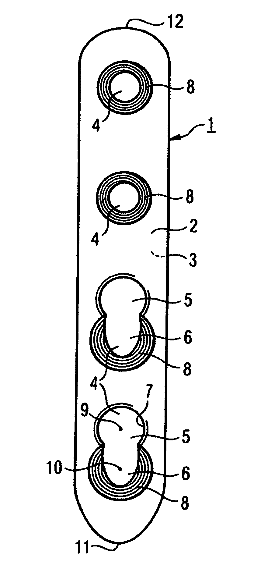
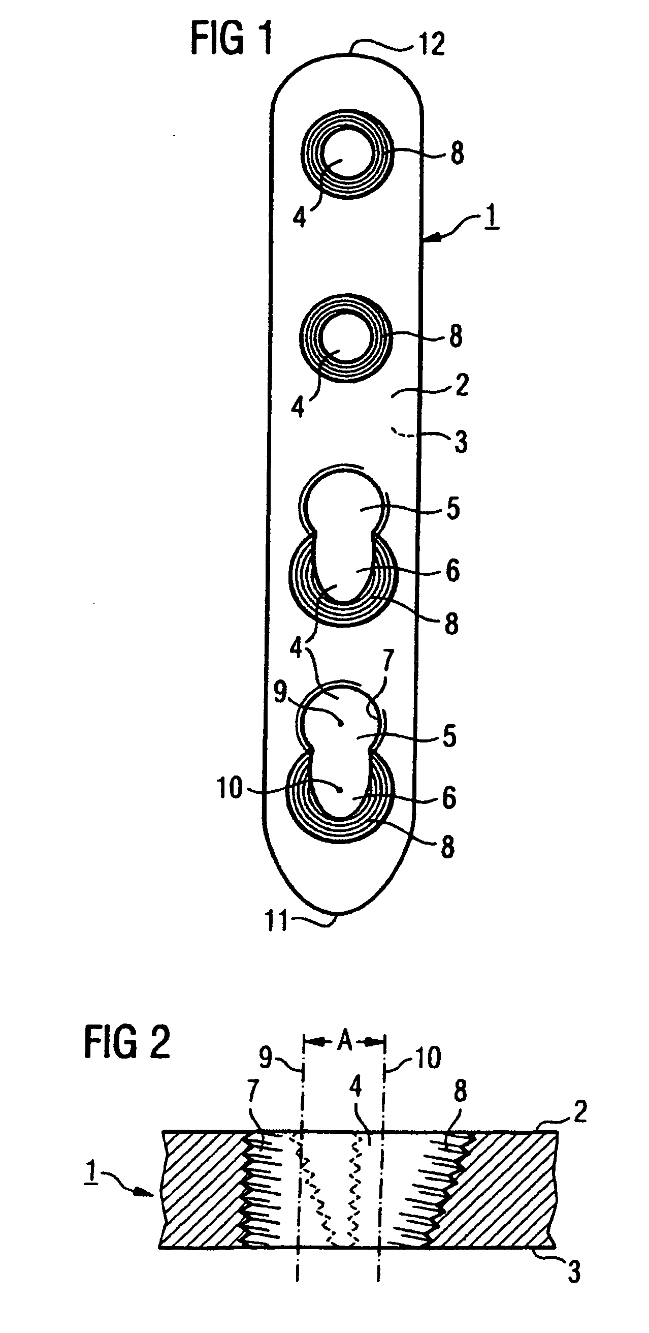
[0040] The bone plate 1 shown in FIGS. 1 and 2 comprises a top side 2. a bottom side 3 facing the bone, a first end 11, a second end 12 and four plate holes which shall receive the bone screws and which are configured between the two ends 11, 12 and connect the top side 2 to the bottom side 3.

[0041] The two plate holes 4 near the first end 11 are constituted by two different and partly overlapping boreholes 5, 6. The first (5) of the two boreholes is circular cylindrical and comprises a cylinder axis 9 and an inside thread 7. The second (6) of the two boreholes tapers from the top side 2 toward the bottom side 3 to subtend a cone frustrum and it comprises a conical axis 10 and an inside thread 8. The cylinder axis 9 and the cone axis 10 run parallel to each other and are a distance A=2 mm apart.

[0042] Of the two plate holes 4 constituted by the overlapping boreholes 5, 6, the terminal one is configured near the first and tapering end 11 of the bone plate 1.

[0043] The plate holes ...


PUM


Abstract

A bone plate (1) having an upper side (2), a bone-sided lower side (3), a first end (11), a second end (12) and several plate holes (4) arranged between the two ends (11, 12) and connecting the upper side (2) to the lower side (3), the plate holes being provided for receiving bone screws. Two of the plate holes (4) are formed by a combination of two partially overlapping boreholes (5, 6) of different type. The first (5) of the two boreholes is a circular cylindrical bore, having an internal thread (7) and a cylinder axis (9). The second borehole (6) has a cone axis (10) and tapers from the upper side (2) to the lower side (3) in the form of a frustum of a cone. The second borehole (6) is provided with an internal thread (8). The cylinder axis (9) is situated at a distance A from the cone axis (10), where A is different than zero.

Description

RELATED APPLICATION DATA [0001] The present application is a continuation of the U.S. National Stage designation of co-pending International Patent Application No. PCT / CH2003 / 000712, filed Oct. 30, 2003, the entire content of which is expressly incorporated herein by reference thereto.FIELD OF INVENTION [0002] The present invention relates to a bone plate and, more particularly, to a bone plate having at least one combination hole formed by two different, partially overlapping through-holes. BACKGROUND OF THE INVENTION [0003] Primarily, the bone plate is intended to fix forefoot osteotomies, in particular hallux valgus osteotomies. Such osteotomies, or their fixations, should obey the following criteria: [0004] they should be angularly fixed, [0005] they should match the corresponding size of the correction, [0006] they should be minimally invasive. [0007] An implant in the form of a clamp is known from the patent documents WO 00 / 06036 and AT 000937U2 and is used intramedullarily. S...

Claims


Application Information

Patent Timeline
IPC IPC(8): A61F2/30A61B17/00A61B17/17A61B17/72A61B17/80A61B17/92
CPCA61B17/00234A61B17/1725A61B17/72A61B17/7233A61B2017/565A61B17/8057A61B17/8061A61B17/921A61B17/7291A61B17/80A61B17/68A61B17/58
Inventor BEUTTER, FLORIANAPPENZELLER, ANDREASCICOIRA, FRANCOFRIGG, ROBERT
Owner SYNTHES USA
Why Eureka
Try Eureka