Combustion transition duct providing stage 1 tangential turning for turbine engines

a technology of transition ducts and turbine engines, which is applied in the direction of machines/engines, liquid fuel engines, lighting and heating apparatus, etc., can solve the problems of complex systems that can be expensive to manufacture, install, and damage the vanes and associated support structures, so as to prevent leakage between adjacent transition duct bodies at least partially

Active Publication Date: 2007-01-25
SIEMENS ENERGY INC
View PDF25 Cites 71 Cited by
  • Summary
  • Abstract
  • Description
  • Claims
  • Application Information

AI Technical Summary

Benefits of technology

[0023] It is thus an object according aspects of the invention to provide a turbine subsystem that eliminates the need for first stage turbine section vanes.
[0032] The outlet regions can be supported by a support ring coupled to the first stage housing. The support ring can be made up of a plurality of support ring segments spaced circumferentially to define the support ring. Each support ring segment can have inner and outer spans joined by a central column defining a lateral opening on either side of the central column. A portion of one of the transition duct bodies can be inserted into the lateral opening, and two adjacent ring segments can be attached to a common one of the transition duct bodies so that the inserted portion of the common transition duct body is substantially surrounded and the junction of adjacent ring segments occurs along an imaginary line across the outlet of the common transition duct body. In this way, leakage between adjacent transition duct bodies can at least partially be prevented. Each support ring segment can include support legs extending from the outer span and connecting to the turbine section support housing. Further, the inner and outer spans and column can provide a sealing system along each lateral opening to seal against the inserted transition duct body portion.

Problems solved by technology

The use of first stage vanes to accelerate and turn the longitudinal gas flow in the circumferential direction present several challenges.
The forces and heat involved can crack and otherwise damage the vanes and associated support structure.
To address these various requirements and operating conditions, the first stage vanes and the associated support structure and cooling systems have developed into a complex system that can be expensive to manufacture, install, and, in the event of damage, repair and replace.

Method used


Image

  • Combustion transition duct providing stage 1 tangential turning for turbine engines
  • Combustion transition duct providing stage 1 tangential turning for turbine engines
  • Combustion transition duct providing stage 1 tangential turning for turbine engines

Examples


Embodiment Construction

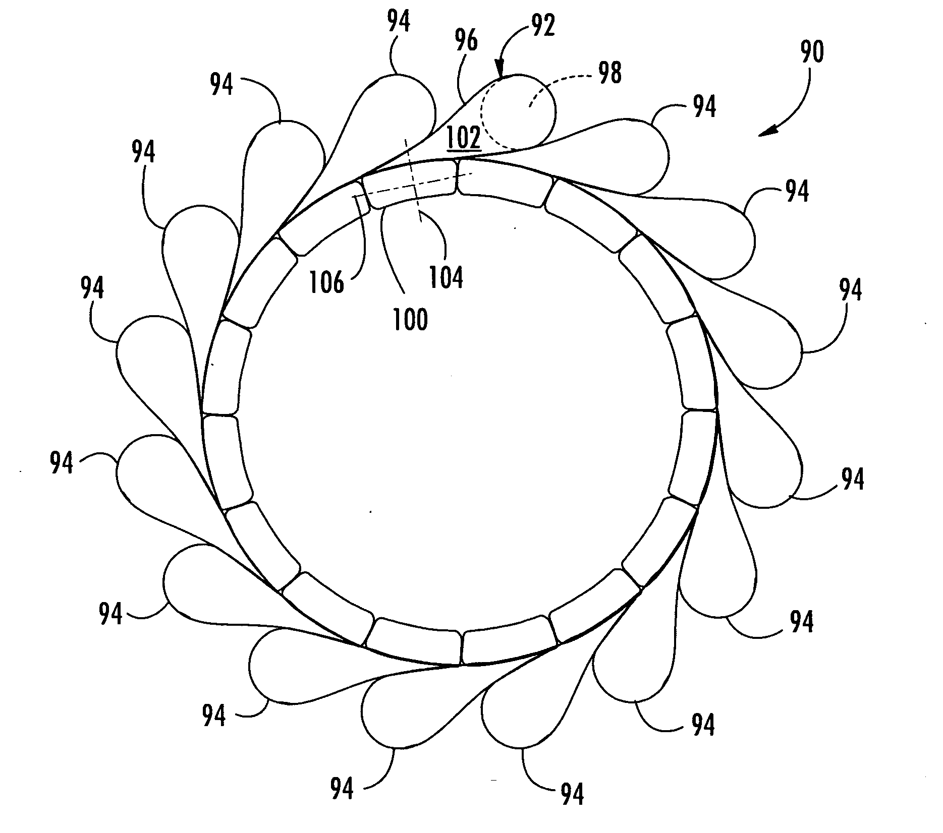
[0045] Embodiments according to aspects of the present invention are directed to combustion turbine transition ducts that impart a tangential component to the gas flow discharged from the transition duct in substitution of the corresponding tangential turning by a first stage vane. Thus, with the use of a transition duct according to aspects of the invention, first stage vanes in an associated turbine engine can be eliminated, avoiding various challenges attendant to use of first stage vanes. According to embodiments of the invention, the transition can be used in a turbine subsystem having a first stage blade array and one or more combustors located longitudinally upstream and radially outboard of the first stage blade array. This subsystem is used in a combustion turbine system having a compressor section, a combustion section and a turbine section with appropriate structure for air intake and turbine exhaust to drive a central rotor for various applications, including electric po...


PUM


Abstract

A transition duct for routing a gas flow from a combustor to the first stage of a turbine section in a combustion turbine engine has an internal passage from an inlet to an outlet that is offset from the inlet in the longitudinal, radial and tangential directions. The offset outlet and the curved internal passage discharge the gas flow toward the first stage blade array at an angle in the tangential direction relative to the longitudinal direction. This angled discharge can be presented directly to the blades, thus avoiding the need for first stage vanes and the associated costs and complexity.

Description

FIELD OF THE INVENTION [0001] The invention relates in general to combustion turbine engines and, more specifically, to transition ducts for routing gas flow from combustors to the turbine section of a combustion turbine engine. BACKGROUND OF THE INVENTION [0002] Referring to FIG. 1, there is shown a cross-section through a portion of a combustion turbine 10. The major components of the turbine are a compressor section 12, a combustion section 14 and a turbine section 16. A rotor assembly 18 is centrally located and extends through the three sections. The compressor section 12 can include cylinders 20, 22 that enclose alternating rows of stationary vanes 24 and rotating blades 26. The stationary vanes 24 can be affixed to the cylinder 20 while the rotating blades 26 can be mounted to the rotor assembly 18 for rotation with the rotor assembly 18. [0003] The combustion section 14 can include a shell 28 that forms a chamber 30. Multiple combustors, for example, sixteen combustors (only...

Claims


Application Information

Patent Timeline
Patent Type & Authority Applications(United States)
IPC IPC(8): F23R3/42
CPCF01D9/023F02C7/20F23R3/425F23R3/60F05D2300/603F05D2250/25F05D2250/31F05D2250/322Y02T50/675Y02T50/60F02C7/00F01D5/12F01D25/00
Inventor BANCALARI, EDUARDOWILSON, JODYLITTLE, DAVID A.FADOK, JOSEPH
Owner SIEMENS ENERGY INC
Why Eureka
Try Eureka