Overhead Suspended Transportation System and Method

a transportation system and suspension technology, applied in the field of transportation systems, can solve the problems of limited speed, limited propulsion and braking force generated in the trucks, and difficulty in detaching or exchanging the car body, so as to reduce the total number of wheels required to carry the train, reduce the weight, and ensure the effect of accurate electrical connection

Inactive Publication Date: 2007-01-25
SKY TRAIN CORP
View PDF31 Cites 9 Cited by
  • Summary
  • Abstract
  • Description
  • Claims
  • Application Information

AI Technical Summary

Benefits of technology

[0019] Carrying vehicles may use a truck at each end of the carrying vehicle using two trucks per vehicle or use single trucks carrying the ends of the adjacent carrying vehicles in an arrangement defined as “articulation”. This articulation allows two vehicles to share the articulating truck, resulting in a reduction in the total number of wheels required to carry the train.
[0020] A closed duct protects the carrying vehicles and the installations therein against climatic conditions, providing a transportation service that continues without interruption from bad climatic conditions such as windstorms, snow and ice storms. Materials for this design may be of many forms with or without channels, pipes or conduits for the placement and transportation of various control or utilities such as fiber optics or street lighting.
[0021] Overhead suspension allow vehicles with suspended car bodies to move overhead and separated from all other functions, allowing the service to be completely automated for safety, reliability and economic operation. If there are segments of a route where the duct may descend low enough for the suspended bodies to travel closer to, the ground when entering a low station platform, a tunnel or subway segment, by way of example. In such a situation the operation ceases to be overhead and fully separated. It is then desirable to have a right of way in such segments of route for an automated operation adequately protected against trespass.
[0022] Embodiments of the present invention illustrated herein by way of example, show that it is a simple matter where applicable to incorporate a system of quick detach into the suspension system so that car bodies may be exchanged according to the needs of various commodities, either passengers or freight. The “Quick Detach” may carry the full weight of the suspended body once it is in place.
[0023] The chassis of the carrying vehicle may be provided with a winch and cable system or other lifting devices such as pneumatic cylinders so that the carrying vehicle may raise or lower the car body without external assistance, facilitating exchange and interchange of bodies, or allowing movement in service of the carrying vehicle without a car body attached beneath it. Such lifting devices do not need to continue carrying the weight of the suspended bodies once the quick detach is locked into place, relieving the weight from the lifting device, but may continue to serve as secondary safety devices in the event of any mechanical complications.
[0024] Embodiments of the quick detach may incorporate guides to ensure correct nesting of the components, so that car bodies with the compatible attachments above can be lifted either by lifting mechanisms incorporated in the chassis or by any contemporary means such as forklift trucks and offered up to the matching attachments on the chassis above and locked into place for safe transportation. Such allows for an accurate mating of electrical connections (if required) between the carrying vehicle and the suspended car or freight vehicle for heating or air conditioning, refrigeration of the container or freight car, door activation, lighting and communications. This nesting function ensures proper mating of the attachments on the body with the attachments on the carrying vehicles when bodies are lifted up to the carrying vehicles. The design quick detach system permits the operation of attaching and locking or unlocking and detaching the car bodies and remote controlling or automation.

Problems solved by technology

This allows the car bodies to swing out in curves but imposes limits on speed because of the suspension system.
The propulsion and braking forces generated in the trucks are limited as a result of the force being transmitted directly down to the car bodies through their suspension attachments.
In such cases the direct suspension of the bodies from the trucks results in difficulties when detaching or exchanging the car bodies.
It also imposes limitations on the ability to couple vehicles into trains because such coupling is done at the car bodies and not at the trucks where the traction forces are generated.
In many places, the work of installing these tracks requires purchase of property, displacement of occupants, and disruption of commercial operations.
In streets, it disrupts traffic movements for long periods of time.
Especially costly is the needed utilities relocation.
In mature cities the location of these is not accurately defined, thus creating expensive and hazardous conditions for workers.
The vehicles become equally delayed because they cannot move any faster than this same congestion.
They introduce risks of collisions, injuries and deaths with vehicles and pedestrians, and impose limits of permissible operating speeds.
There are strict limits on the lengths and speeds of trains in the streets, and on the frequency of trains, making it difficult to expand capacity to meet future growth.
Typical vehicle designs attempt to minimize this effect, but do not eliminate it.
Bottom-supported vehicles impose strict limitations on an amount of super-elevation to be tolerated on curves, directly impacting permissible speeds of vehicles traversing curves.

Method used


Image

  • Overhead Suspended Transportation System and Method
  • Overhead Suspended Transportation System and Method
  • Overhead Suspended Transportation System and Method

Examples


Embodiment Construction

[0043] The present invention will now be described more fully with reference to the accompanying drawings in which preferred embodiments of the invention are shown and described. It is to be understood that the invention may be embodied in many different forms and should not be construed as limited to the illustrated embodiments set forth herein. Rather, these embodiments are provided so that this disclosure may be thorough and complete, and will convey the scope of the invention to those skilled in the art.

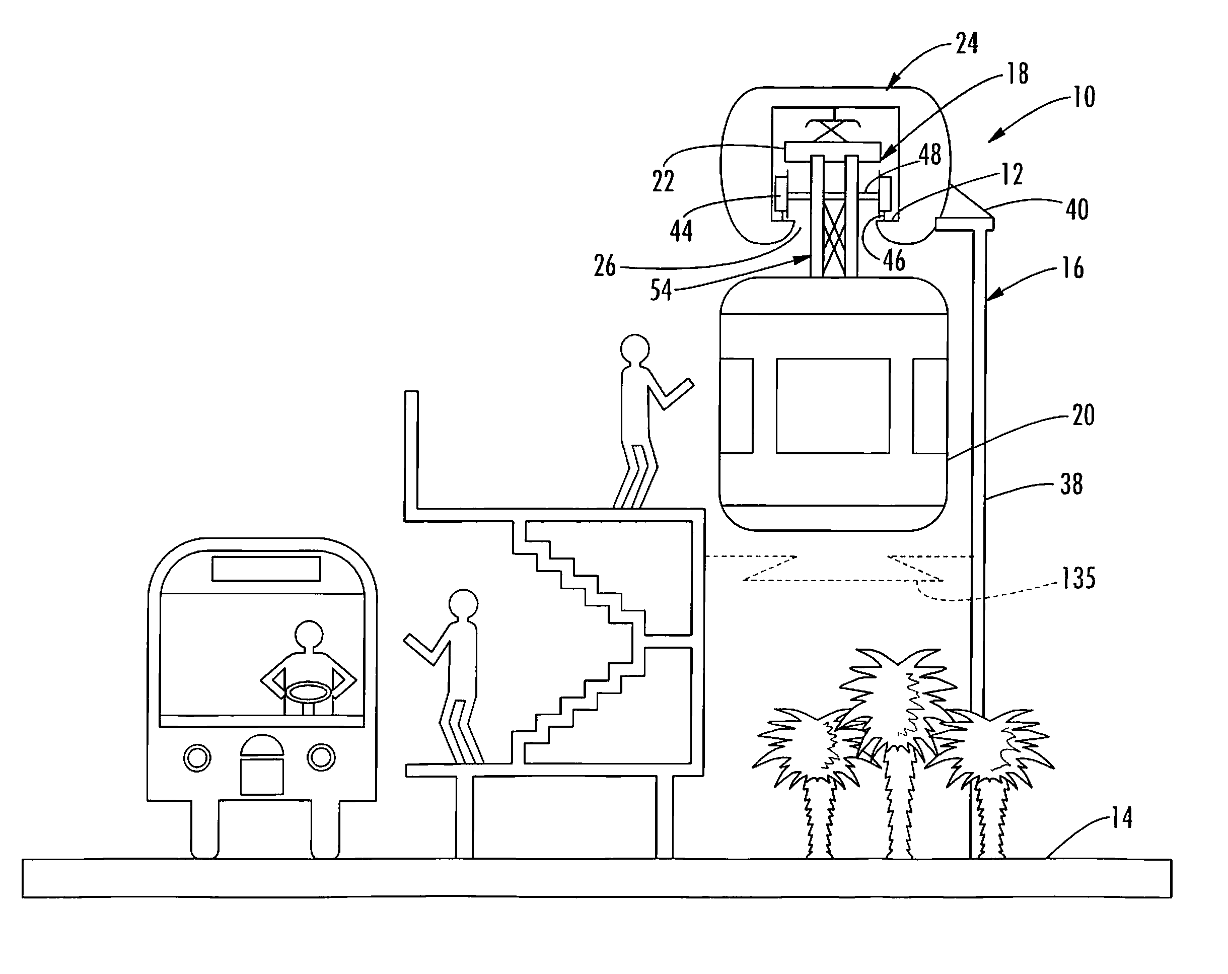
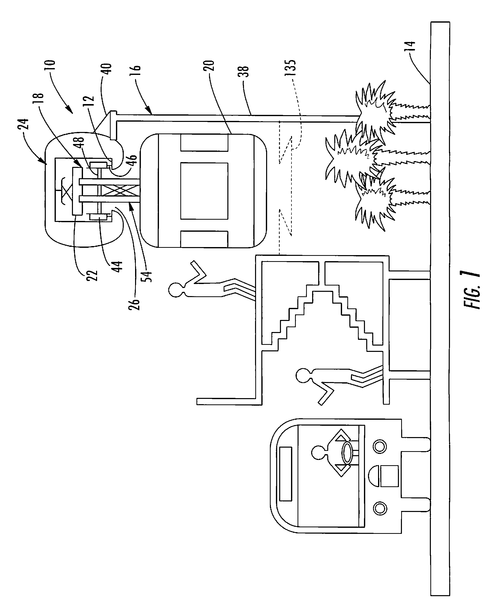
[0044] With reference initially to FIG. 1, a transportation system 10 following the teachings of the present invention may include a running surface 12 suspended above ground level 14 by a support structure 16. A truck 18, also known as a bogie, is operable along the running surface 12. As herein described by way of example, a car body 20 may be suspended from a chassis 22 carried by the truck 18 for suspending the car body above the ground level 14. As will be further described...


PUM


Abstract

An overhead transportation system includes a support structure positioning a running surface above ground level for operating a truck along the running surface. A car body is suspended from a beam or chassis carried by the truck in such a manner to place a center of rotation of the car body above the chassis and truck. Improved performance on curves is provided through superelevation of the tracks upon which fixed steel wheel assemblies of the truck ride.

Description

CROSS REFERENCE TO RELATED APPLICATION [0001] This application is a Continuation of application Ser. No. 10 / 685,300 filed Oct. 14, 2003 which claims priority to Provisional Application Ser. No. 60 / 418,872 for “Vehicle Overhead Suspension System And Method Having Enhanced Performance On Curves” having a filing date of Oct. 15, 2002, the disclosures of which are herein incorporated by reference in their entirety and commonly owned.FIELD OF THE INVENTION [0002] The invention generally relates to transport systems, and more particularly to high-speed mass transit, passenger and freight transportation systems that are suspended overhead above ground level. BACKGROUND OF THE INVENTION [0003] Overhead-suspended systems are known in the art and currently in operation. Typically, car bodies are suspended directly from and below trucks. In one case the trucks have steel wheels running on top of a single steel rail, being truly a “Monorail”. This allows the car bodies to swing out in curves bu...

Claims


Application Information

Patent Timeline
Patent Type & Authority Applications(United States)
IPC IPC(8): E01B27/00
CPCE01B25/22
Inventor GUENTHER, KARLSERGEANT, WILFRED P.E.
Owner SKY TRAIN CORP
Why Eureka
Try Eureka