Active intake and induction system

a technology of induction system and intake manifold, which is applied in the direction of air intake for fuel, combustion-air/fuel-air treatment, machines/engines, etc., can solve the problems of undesirable noise created by the intake manifold, and achieve the effect of reducing engine noise, reducing oxygen reaching the engine, and improving efficiency performan

Inactive Publication Date: 2007-01-25
SIEMENS VDO AUTOMOTIVE INC
View PDF17 Cites 2 Cited by
  • Summary
  • Abstract
  • Description
  • Claims
  • Application Information

AI Technical Summary

Benefits of technology

[0007] When the inlet valve is in the open position air can flow freely through the air inlet and into the air cleaner. When the engine RPMs drop below a predetermined limit, the inlet valve is moved toward the closed position. When the inlet valve is in the closed position airflow is restricted. The amount of oxygen reaching the engine is reduced. The restricted airflow through the air inlet helps to reduce engine noise when the engine is operating at lower RPMs.
[0008] As the RPMs of the engine increase the actuator senses the change. The valve shaft and inlet valve move from the closed position to the open position to allow unrestricted airflow to the air cleaner. Thus, the engine is provided with more oxygen allowing more efficient performance to occur.

Problems solved by technology

Noise created by the intake manifold is undesirable.

Method used


Image

  • Active intake and induction system
  • Active intake and induction system
  • Active intake and induction system

Examples


Embodiment Construction

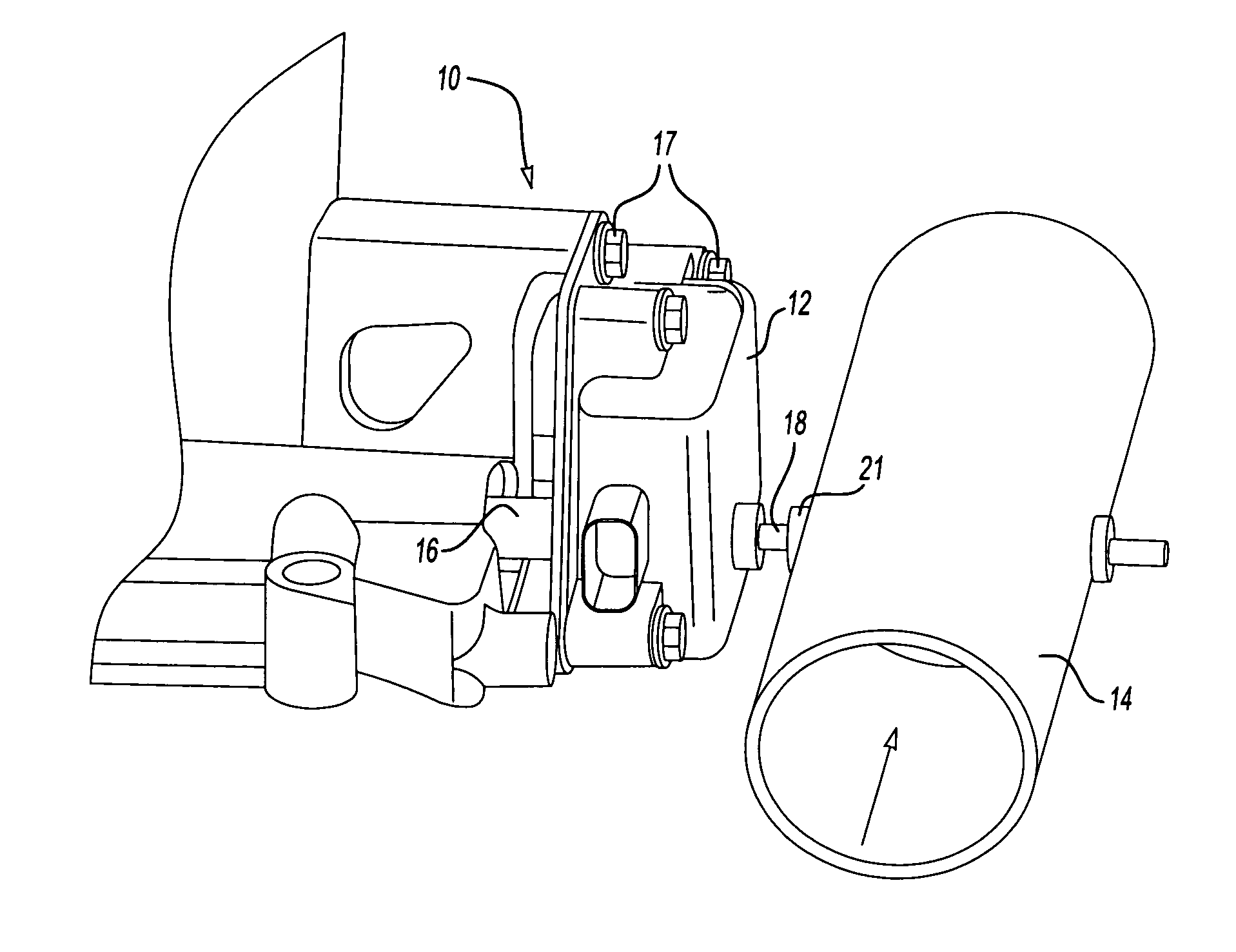
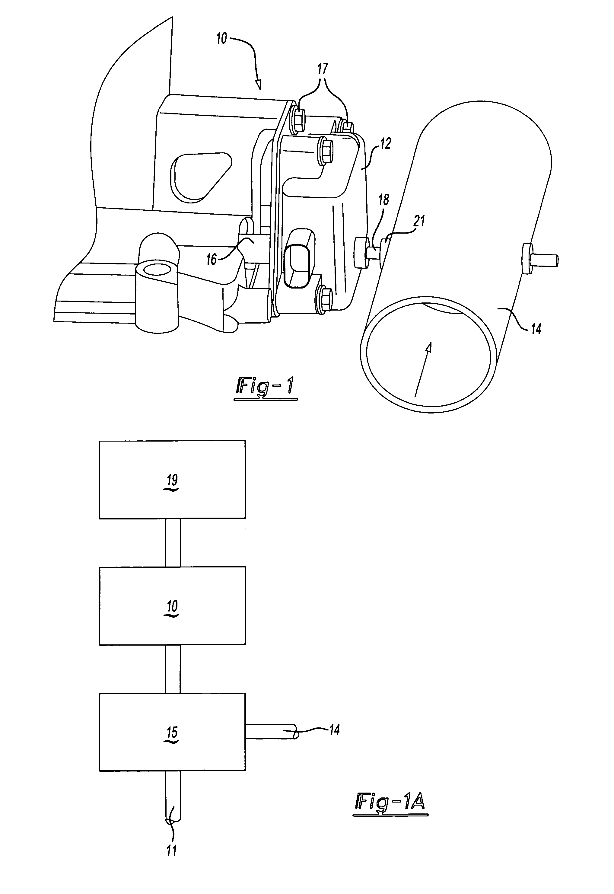
[0015]FIG. 1 shows an intake manifold assembly 10, an actuator 12, and a secondary air inlet 14. The actuator 12 is mounted to the intake manifold assembly 10 using fasteners 17. The air inlet 14 is mounted adjacent to the actuator 12 and the intake manifold assembly 10. The air inlet 14 leads to and is supported by an air cleaner housing 15.

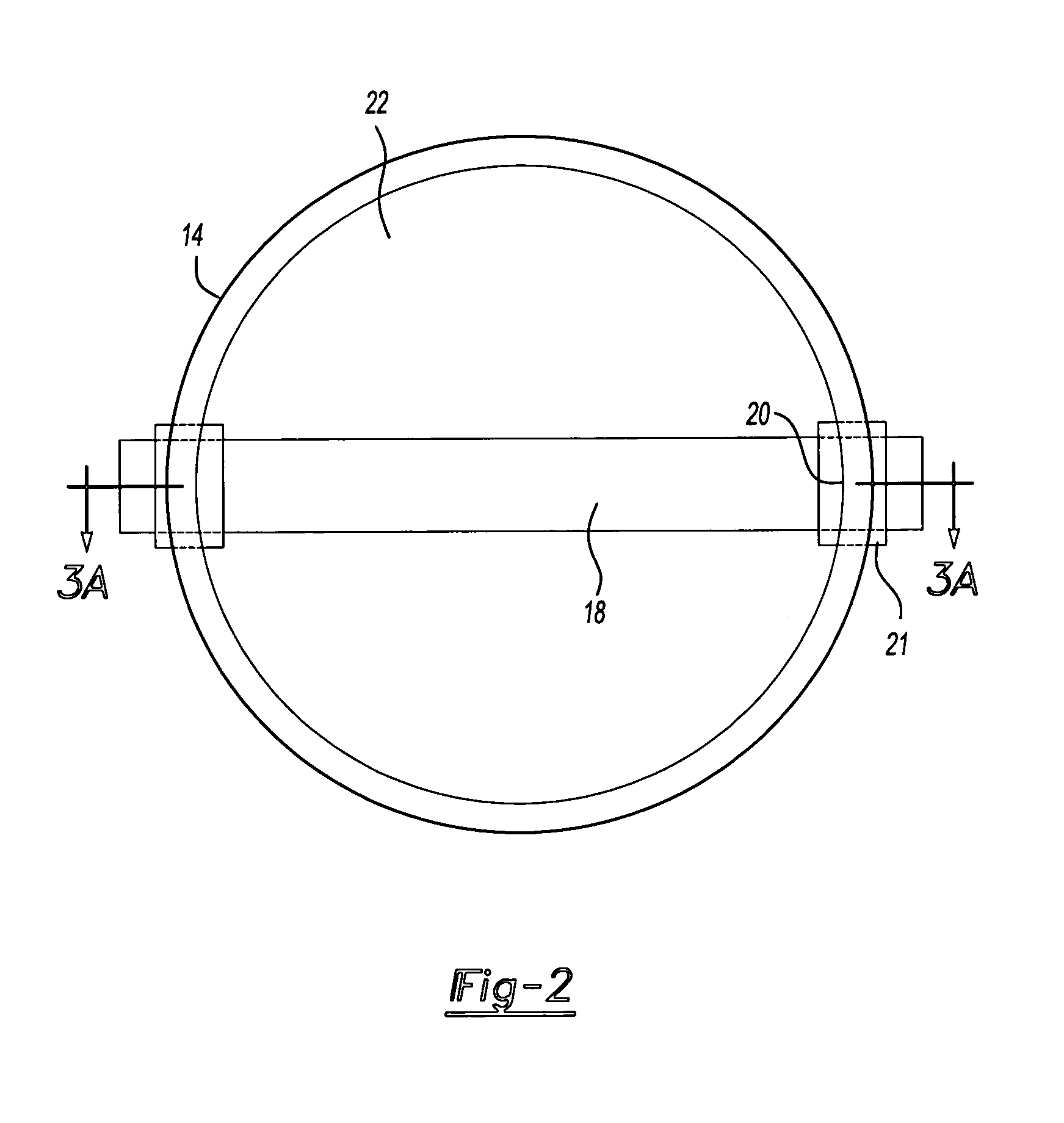
[0016] Extending from the actuator 12 in a first direction is a main shaft 16. The actuator controls the main shaft 16 to open or close the main air inlet of the intake manifold assembly 10. A valve shaft 18 extends from an opposing side of the actuator 12. The valve shaft 18 extends into the air inlet 14 through openings 20 (shown in FIG. 2). Bearings 21 located at the openings 20 provide support for the valve shaft 18 while supporting the valve shaft 18 for rotation.

[0017] Referring to FIG. 1A passage of air from the secondary air inlet 14 to the engine 15 is shown schematically. Air enters the air inlet 14 and flows through the air inlet 14...


PUM


Abstract

An air inlet is mounted adjacent to an actuator and an intake manifold. A valve shaft extending from the actuator to the air inlet rotates the inlet valve from an open position to a closed position, or vice versa. The actuator senses revolutions per minute of an engine to control the inlet valve position. When the inlet valve is in the closed position the amount of oxygen reaching the engine is reduced. The restricted airflow through the air inlet helps to reduce engine noise.

Description

BACKGROUND OF THE INVENTION [0001] The invention is an arrangement for controlling airflow within a secondary air inlet in intake manifolds. [0002] Intake manifolds control the amount of air entering internal combustion engines. Air enters the intake manifold and flows through to the engine. Intake manifolds use shaft and blade assemblies to control the intake of air into the manifold assembly from a main air inlet. A manifold housing usually has a secondary air inlet, which leads to an air cleaner. [0003] At lower engine revolutions per minute (RPM) less air is needed within the engine. Maximum airflow through the main air inlet and secondary air inlet is not required. Noise created by the intake manifold is undesirable. However, at higher engine RPM more oxygen is needed to support engine performance. Airflow into the intake manifold must be increased to obtain the desired amount of oxygen within the engine. [0004] An arrangement for reducing air inflow into an intake manifold at ...

Claims


Application Information

Patent Timeline
Patent Type & Authority Applications(United States)
IPC IPC(8): F02M35/10
CPCF02M23/003Y02T10/146F02M23/006Y02T10/12
Inventor LETOURNEAU, MARKPETTIPIECE, JASON
Owner SIEMENS VDO AUTOMOTIVE INC
Why Eureka
Try Eureka