
Double-air-gap ozone generating device

An ozone generating device and double air gap technology, applied in the field of ozone preparation, can solve the problems of high operating cost, high power consumption of the ozone generator, and low discharge efficiency of the discharge unit, so as to increase the discharge area, increase the ozone concentration and the ozone Effects of productivity, reduction of manufacturing cost and running cost

Inactive Publication Date: 2013-06-19
JIANGSU KONER OZONE
View PDF0 Cites 10 Cited by
  • Summary
  • Abstract
  • Description
  • Claims
  • Application Information

AI Technical Summary

Problems solved by technology

Due to the constraints of the manufacturing and assembly process level, most enterprises are difficult to guarantee the geometric accuracy of the discharge body at a specific length, resulting in low discharge efficiency of the discharge unit, large power consumption of the ozone generator, and high operating costs

Method used


Image

  • Double-air-gap ozone generating device
  • Double-air-gap ozone generating device

Examples


Embodiment Construction

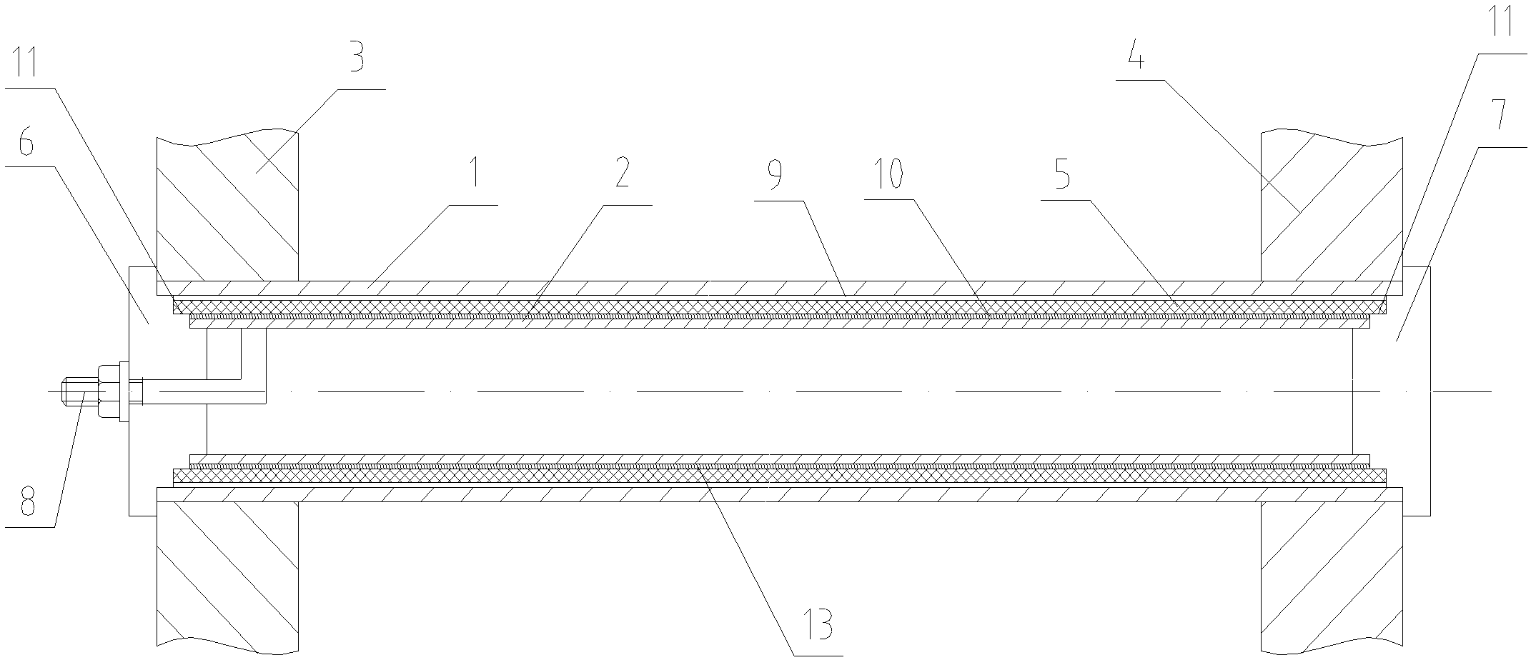
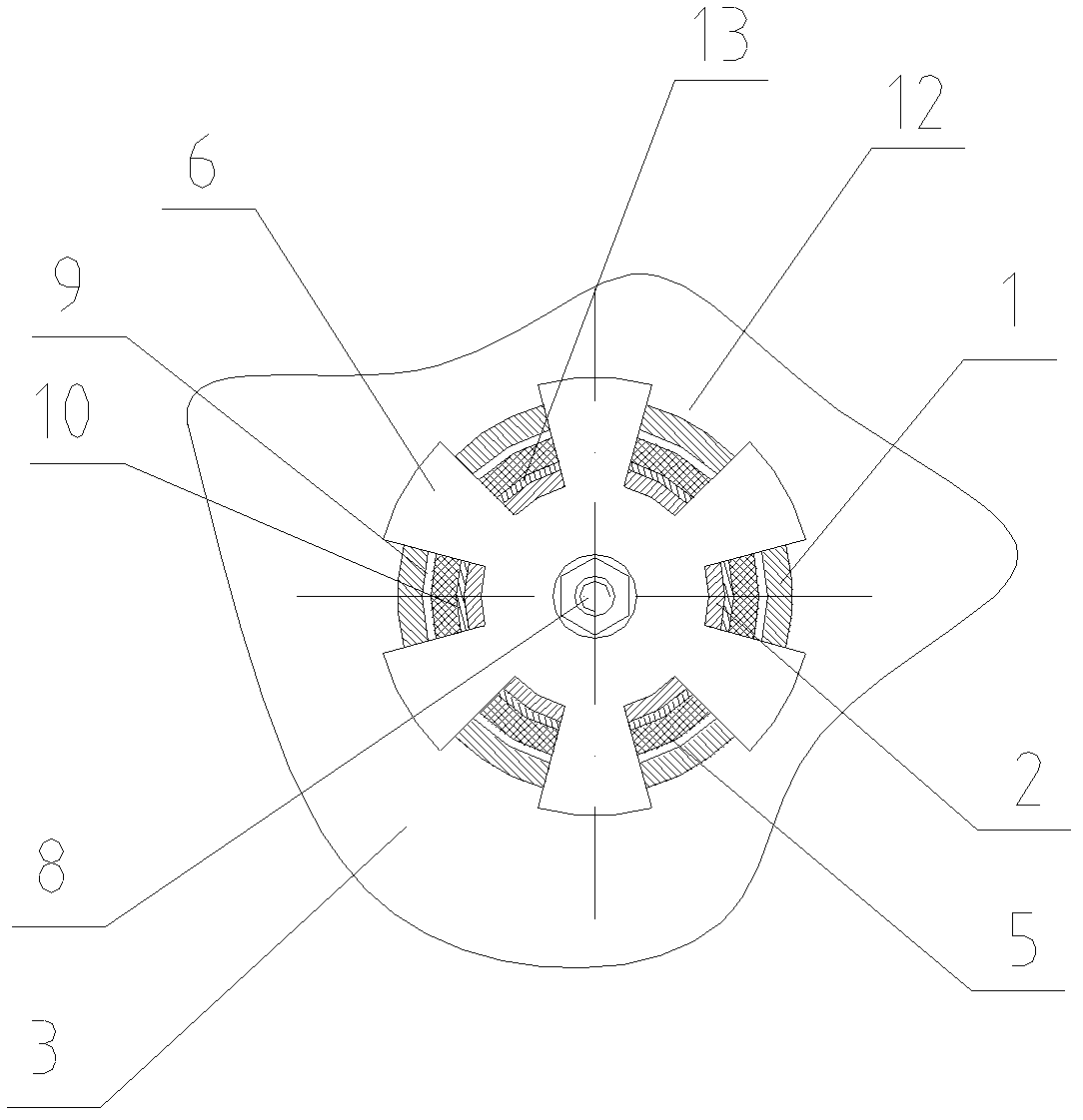
[0010] The present invention will be further described below in conjunction with the accompanying drawings. As shown in the figure, a double-air-gap ozone generator includes a cylindrical outer electrode 1, an inner electrode 2 installed inside the outer electrode 1, and is used to support the outer electrode 1 and conduct electricity. The left flower plate 3 and the right flower plate 4, the glass dielectric tube 5 between the outer electrode 1 and the inner electrode 2, the left end cap 6 and the right end cap 7 for fixing the inner and outer electrodes 1, 2 and the glass dielectric tube 5 , the electrode 8 connected to the inner electrode 2 through the left end cover 6, the gap between the outer electrode 1 and the glass dielectric tube 5 is the outer air gap 9, and the gap between the glass dielectric tube 5 and the inner electrode 2 is the inner air The left and right end caps 6, 7 are provided with three limiting steps 11 on opposite sides, and the left and right end caps...


PUM


Abstract

A double-air-gap ozone generating device comprises a barrel-shaped outer electrode, an inner electrode which is arranged inside the outer electrode, a left pattern plate, a right pattern plate, a medium pipe which is arranged between the outer electrode and the inner electrode, a left end cover, a right end cover and an electrode which penetrates through the left end cover and is connected with the inner electrode, wherein the left pattern plate and the right pattern plate are used for supporting the outer electrode, the left end cover and the right end cover are used for fixing the inner electrode, the outer electrode and the medium pipe, the gap between the outer electrode and the medium pipe is an outer gap, the gap between the medium pipe and the inner electrode is an inner gap, three position limiting steps are arranged on one sides, oppositely arranged, of the left end cover and the right end cover, and axial grooves are formed in the left end cover and the right end cover along the axial line direction. The double air gap ozone generation device has the advantages that under the situation that the size of the volume of a discharging unit is unchanged, the size of discharging area is multiply increased, ozone concentration and ozone generating efficiency are improved, and the manufacture cost and the operation cost of the ozone generator are reduced.

Description

technical field [0001] The invention relates to an ozone generating device, in particular to a double-gap ozone generating device integrating dielectric barrier discharge and surface discharge, which is suitable for use in large-scale ozone generators above the kilogram level and with multiple discharge units, and belongs to ozone preparation field. Background technique [0002] In the field of ozone, most of the large-scale ozone generators currently use a single dielectric barrier discharge unit mode, and its operating efficiency largely depends on the rationality of the structure of a single discharge unit, which is mainly manifested in: 1. The length of the discharge path ; 2. The material and geometric accuracy of the discharge body; 3. The size and uniformity of the discharge air gap; 4. The discharge type, etc. Due to the constraints of the manufacturing and assembly process level, most enterprises are difficult to guarantee the geometric accuracy of the discharge bo...

Claims


Application Information

Patent Timeline
Patent Type & Authority Applications(China)
IPC IPC(8): C01B13/11
Inventor 乐飞孙荣生
Owner JIANGSU KONER OZONE
Learn More