Lifting body aircraft and reentry vehicle with chines

a lifting body and reentry vehicle technology, applied in the field of aircraft, can solve the problems of reducing the pressure above the upper surface affecting the overall upward force of the lifting body, and causing significant air to be displaced up and around the body of the vessel, etc., and achieves the effect of convenient installation, rapid adaptation, and efficient servi

Inactive Publication Date: 2007-01-25
LEIER DUANE
View PDF0 Cites 13 Cited by
  • Summary
  • Abstract
  • Description
  • Claims
  • Application Information

AI Technical Summary

Benefits of technology

[0029] The inventors contemplate that the airframe will be of a single component aeroshell, with modular interior component systems. These internal component systems may include crew modules, control modules, supply modules, cargo modules, satellite modules, medical modules, evacuation modules, science or laboratory modules, propulsion modules, fuel modules, and sub systems modules, or other payload modules. All modules will preferably be designed to be readily installed, removed, and exchanged using standardized mating points and mating adapters. These will allow the vehicle to be efficiently serviced and quickly adapted to changing mission objectives, whether on the ground, in the field, or even on orbit.

Problems solved by technology

As the crafts move through air, the high profile of their curved lower surfaces causes a significant amount of air to be displaced up and around the body of the vessel.
First, pressure is being exerted on the air mass at the interface with the hull.
This will result in a decrease in pressure above the upper surface of the lifting body.
The difference between the increased pressure generated on the lower surface and the decreased pressure at the upper surface will result in an overall upward force on the lifting body.
Although lift bodies were previously known, limited maneuverability and stability of many of the craft in atmospheric flight created significant challenges.
Moreover, the inventors are not aware of any that were ever able to takeoff under their own power.

Method used


Image

  • Lifting body aircraft and reentry vehicle with chines
  • Lifting body aircraft and reentry vehicle with chines
  • Lifting body aircraft and reentry vehicle with chines

Examples


Embodiment Construction

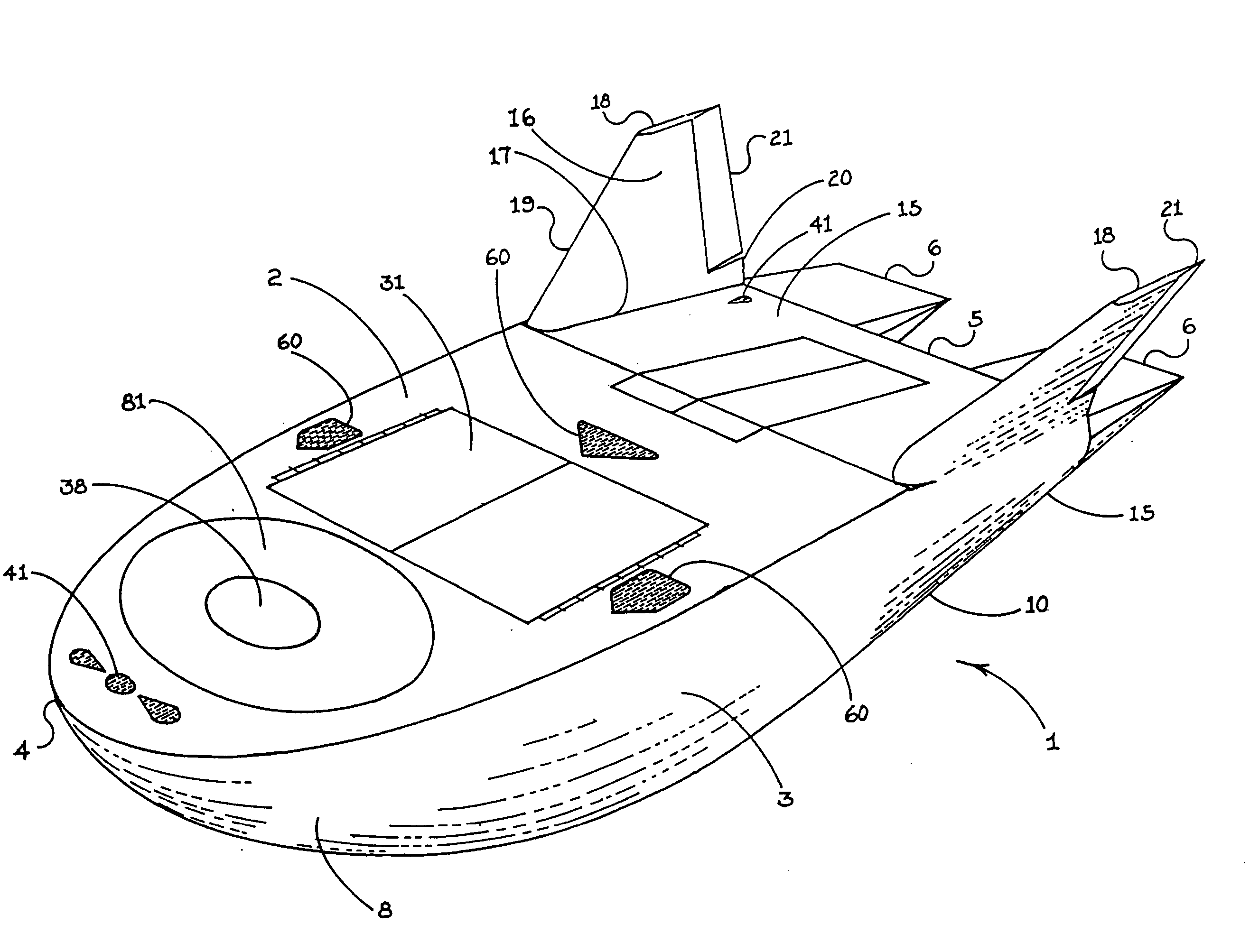
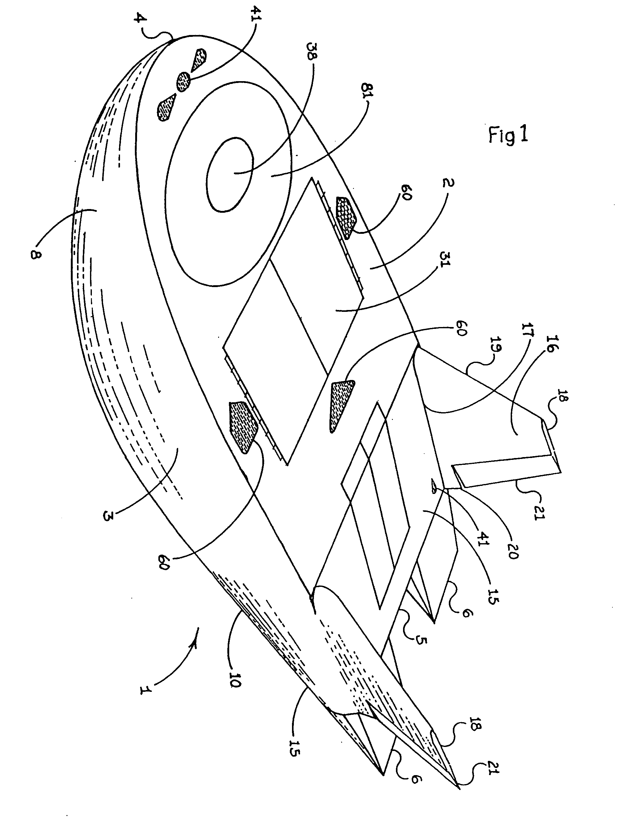
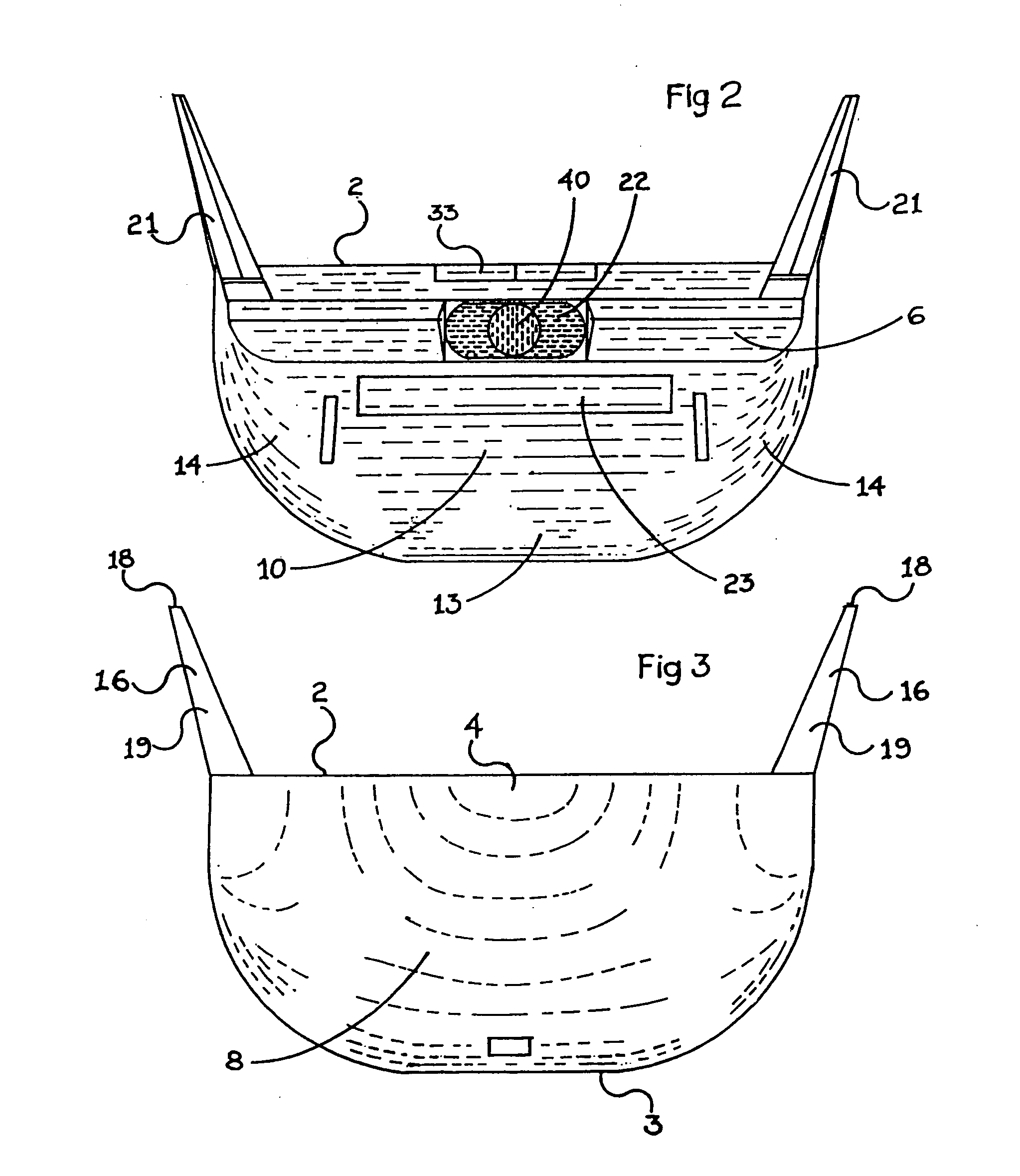
[0056] The invention comprises a lifting body aircraft 1 having an upper surface 2 and a lower surface 3. Upper surface 2 extends from the nose 4 to the tail 5 of craft 1. The length of craft 1 is that dimension extending from nose 4 to tail 5, excluding any elevons 6 (discussed below) which may be provided at the tail end or aft end 7 of craft 1.

[0057] Lower surface 3 has a first half 8 extending from nose 4 to about the longitudinal center line 9 of craft 1. The longitudinal center line 9 of craft 1 is determined by a plane severing craft 1 perpendicular to the length of craft 1 at the half way point between nose 4 and tail 5. Lower surface 3 also has a second half 10 extending from about longitudinal center line 9 to tail 5.

[0058] Upper surface 2 has a pair of edges 11 that extend from nose 4 to tail 5 such that nose 4, edges 11, and tail 5 demark upper surface 2. Edges 11 also demark two boundaries between upper surface 2 and lower surface 3. Edges 11 preferably run from nose ...


PUM


Abstract

A lifting body aircraft suitable for atmospheric flight and/or as a reentry vehicle. The craft has a substantially flat upper surface, a lower surface with a doubly convex first section and a flat sloping second section. Chines may be provided between the upper and lower surfaces. The doubly convex first section allows the craft to have its center of gravity forward of its longitudinal center line. The flat sloping second half of the lower surface and the substantially flat upper surface form the aft end of an airfoil. A pair of vertical stabilizers enhance stability and include rudders which, along with a pair of elevons, provide steerage. The craft may glide or it may have an engine or rockets for thrust. The result is an extremely stable lifting body design that is well suited for launch or conventional take off, insertion, orbital operations, reentry, atmospheric flight, and conventional landings.

Description

CONTINUATION STATUS [0001] This is a continuation-in-part of allowed U.S. patent application Ser. No. 10 / 458,142, which is hereby incorporated by reference in its entirety.BACKGROUND OF THE INVENTION [0002] 1. Field of the Invention [0003] The invention relates to aircraft in general and to lifting body aircraft in particular. [0004] 2. Prior Art [0005] Lifting body aircraft are known in the art. The theory was pioneered by Dr. Alfred J. Eggers, Jr. who discovered that lift could be generated by modifying the shape of a blunt nose cone reentry vehicle. Eggers' theories led to several NASA and U.S. Air Force experimental aircraft in the 1960's and 1970's, namely the M2-F1, the M2-F2, the M2-F3, HL-10, X-24A and X-24B. Eggers' lift concept can also be seen in U.S. Pat. No. 3,276,722. All of these craft generate lift with the fuselage of the aircraft only; i.e. without a wing. [0006] The Eggers craft can generally be described as conical sections. They have a blunt nose, swept back sid...

Claims


Application Information

Patent Timeline
Patent Type & Authority Applications(United States)
IPC IPC(8): B64C1/00
CPCB64G1/14
Inventor STEPHENSON, JON C.
Owner LEIER DUANE
Why Eureka
Try Eureka