Head mounted apparatus
a head and hat technology, applied in the direction of headwear caps, protective garments, hats, etc., can solve the problems of unstable attachment, user discomfort, different left and right adjustment amounts, etc., and achieve the effect of simple structure and good mounting and manipulating capabilities
- Summary
- Abstract
- Description
- Claims
- Application Information
AI Technical Summary
Benefits of technology
Problems solved by technology
Method used
Image
Examples
first embodiment
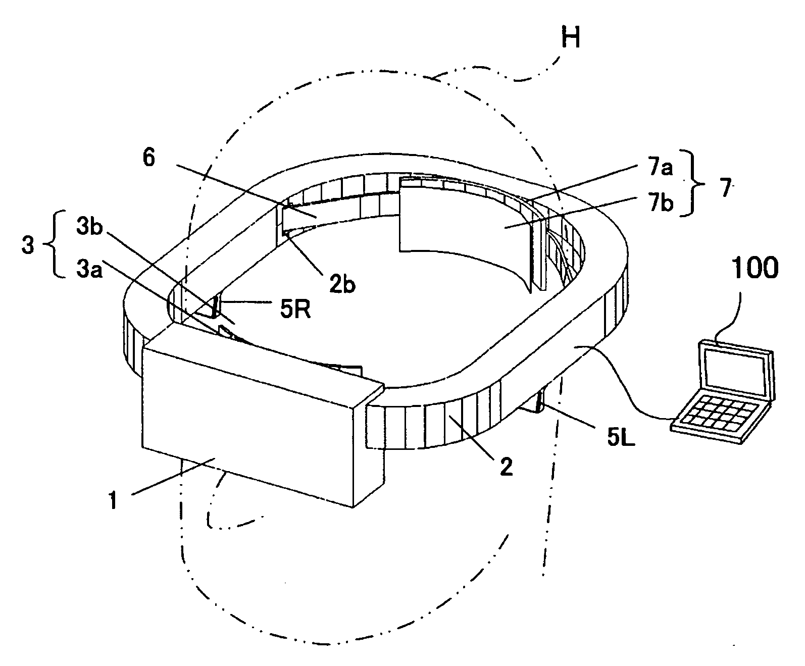
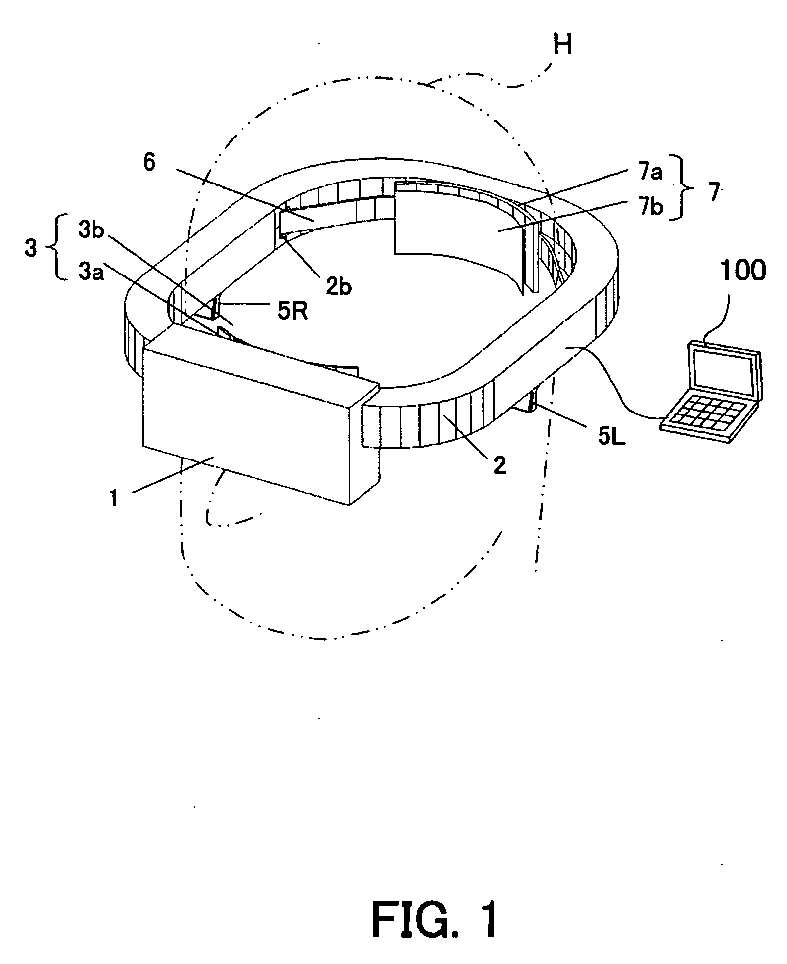
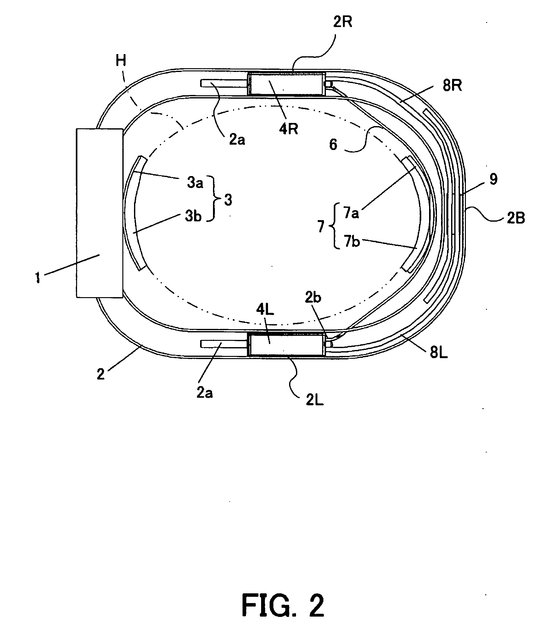
[0022]FIG. 1 shows a head mounted display as a head mounted apparatus according to a first embodiment of the present invention. FIG. 2 shows an internal structure of a frame in the mount mechanism in the head mounted display.
[0023] The head mounted display body or apparatus body 1 is arranged in front of a viewer's head H or eyes. Responsive to an image signal from an image supply apparatus 100, such as a personal computer (“PC”) and a DVD player, the head mounted display body 1 includes, as shown in FIG. 1, an image on an inside display device, such as a liquid crystal panel. An inside optical system magnifies and displays the image on the display device.
[0024] In the following description, the front, back, left, right, top and bottom correspond to those of the head H mounted with the head mounted display. The longitudinal direction can be a direction from the front to the back, and the lateral direction can be a direction from the left to the right.
[0025]2 denotes a rigid frame...
second embodiment
[0050]FIG. 7 shows a head mounted display as a head mounted apparatus according to a second embodiment of the present invention. FIG. 8 shows an internal structure of a frame in the mount mechanism in the head mounted display. This embodiment designates the same reference numerals the elements similar to those in the first embodiment, and omits a description.
[0051]21 denotes a U-shaped frame shape when viewed from a top. The head mounted display body 1 is fixed onto a front portion of the frame 21. The front compressing portion 3 similar to that in the first embodiment is attached to an approximately center in the lateral direction on a plane opposite to the head mounted display 1 at the front portion of the frame 21. The frame 21 has a rectangular frame section in the longitudinal direction, similar to the first embodiment.
[0052] The left and right adjuster 4L and 4R are housed in longitudinally extending portions at the left and right sides of the frame 21 or in the left and rig...
PUM
 Abstract
Description
Claims
Application Information
 - R&D
- Intellectual Property
- Life Sciences
- Materials
- Tech Scout
- Unparalleled Data Quality
- Higher Quality Content
- 60% Fewer Hallucinations
Browse by: Latest US Patents, China's latest patents, Technical Efficacy Thesaurus, Application Domain, Technology Topic, Popular Technical Reports.
© 2025 PatSnap. All rights reserved.Legal|Privacy policy|Modern Slavery Act Transparency Statement|Sitemap|About US| Contact US: help@patsnap.com


