Systems and methods for determining the location and angular orientation of a hole with an obstructed opening residing on a surface of an article

a technology of a surface and an opening, applied in the field of systems and methods for determining the location and angular orientation of an obstructed opening on the surface of an article, can solve the problems of deteriorating components, eventually being restored or replaced altogether, and new coating partially or wholly obstructing the opening of the original film cooling hol

Active Publication Date: 2007-01-25
RAYTHEON TECH CORP
View PDF8 Cites 25 Cited by
  • Summary
  • Abstract
  • Description
  • Claims
  • Application Information

AI Technical Summary

Benefits of technology

[0013] Provided are systems and methods for determining both the location and angular orientation of holes with openings on a surface of an article that are at least partially obstructed. In a method of the present invention, a scanning system including a laser spot projector, a laser spot sensor, a memory device and a processor are provided. A laser beam is projected onto the s...

Problems solved by technology

Despite the use of film cooling and thermal barrier coating, some components deteriorate over time and must eventually be restored or replaced altogether.
Unfortunately, the application of the new coating partially or wholly obstructs the openings of the original film cooling holes.
Even the slightest obstruction can negatively affect the film cooling of the component surfaces.
There are many challenges involved with determining the location and angular orientation of film cooling holes with obstructed openings.
Third, the hole openings are located on complex, three-dimensional surfaces that may vary slightly from component...

Method used


Image

  • Systems and methods for determining the location and angular orientation of a hole with an obstructed opening residing on a surface of an article
  • Systems and methods for determining the location and angular orientation of a hole with an obstructed opening residing on a surface of an article
  • Systems and methods for determining the location and angular orientation of a hole with an obstructed opening residing on a surface of an article

Examples


Embodiment Construction

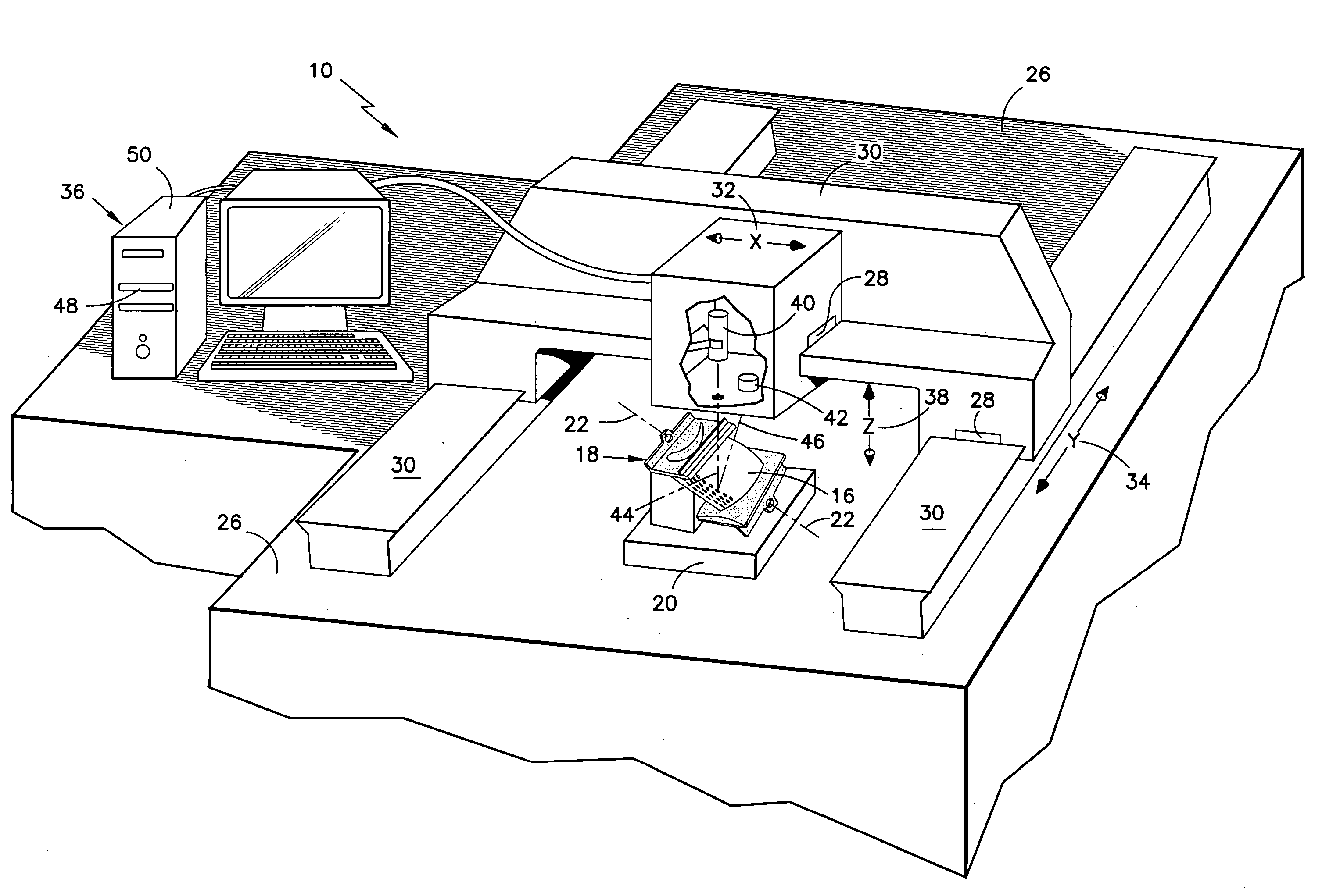
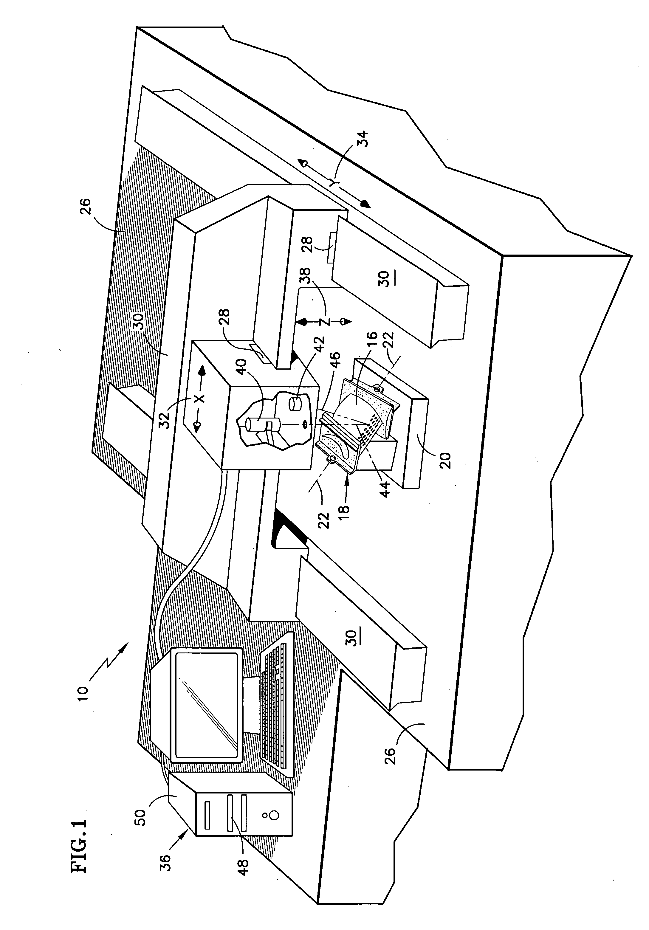
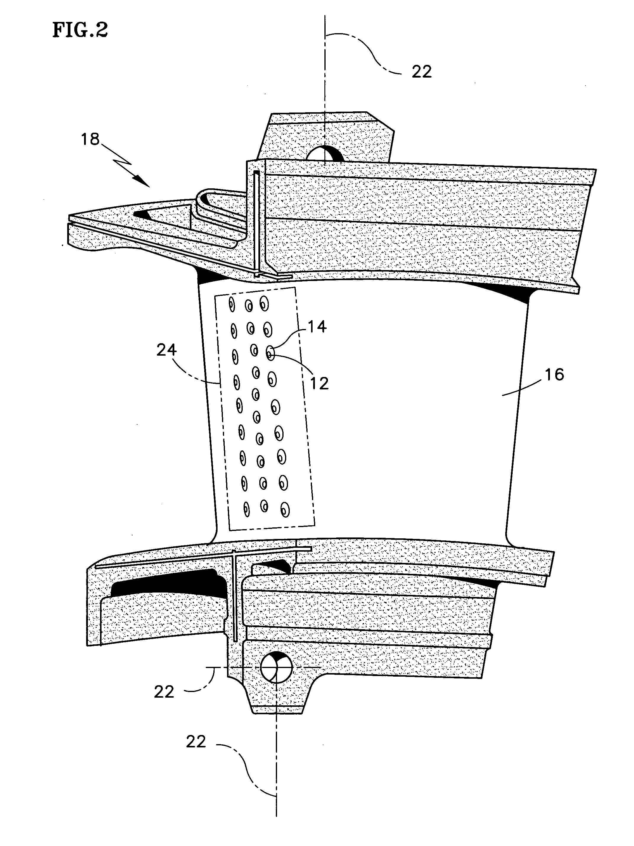
[0021] As illustrated in FIG. 1, a laser scanning system 10 according to an embodiment of the present invention is used to determine the location and angular orientation of one or more holes 12 with obstructed openings 14 on a surface 16 of a typical article 18 as illustrated in FIG. 2. In the example shown, the article 18 is a vane for use inside a gas turbine engine. A stationary fixture 20 accurately establishes the location of the article 18 according to one or more preexisting article datums 22. A region 24 of the surface 16 containing the holes 12 and openings 14 is oriented for maximum exposure to the system 10. The use of an accurate fixture 20 is extremely important, since the resulting hole 12 locations and angular orientations are calculated and stored in relation to the one or more datums 22.

[0022] A multi-axis controller 26, commonly used throughout industry for accurate positioning during machining, measurement and other operations, carries the fixture 20 and article ...


PUM

PropertyMeasurementUnit
Distanceaaaaaaaaaa
Lightaaaaaaaaaa

Abstract

Provided are systems 10 and methods 100 for determining both the location and angular orientation of holes 12 with openings 14 on a surface 16 of an article 18 that are at least partially obstructed. In a method of the present invention, a scanning system 10 that includes a laser spot projector 40, a laser spot sensor 42, a memory device 48 and a processor 50 is provided. A laser beam 44 is projected onto the surface 16 of the article 18 in a region 24 containing at least one hole 12 and the spot sensor receives light reflections 46. A series of points 52 representing the scanned region is stored as a point cloud 54 in the memory device 48. The point cloud 54 is then manipulated to calculate the location and angular orientation of each hole in the region in relation to one or more pre-existing, article datums 22.

Description

CROSS-REFERENCE TO RELATED APPLICATIONS [0001] This application discloses subject matter related to copending US patent application “THERMAL IMAGING AND LASER SCANNING SYSTEMS AND METHODS FOR DETERMINING THE LOCATION AND ANGULAR ORIENTATION OF A HOLE WITH AN OBSTRUCTED OPENING RESIDING ON A SURFACE OF AN ARTICLE.” (APPLICANT REFERENCE NUMBER EH-11506), filed concurrently herewith.BACKGROUND OF THE INVENTION [0002] (1) Field of the Invention [0003] The invention relates to gas turbine engine components, and more particularly to systems and methods for determining the location and angular orientation of a hole containing an obstructed opening on a surface of such components. [0004] (2) Description of the Related Art [0005] Many internal components of gas turbine engines are exposed to gas temperatures that exceed their base material's melting temperature. For that reason, internal components such as turbine rotor blades, turbine stator vanes, combustor liners, shroud segments and the ...

Claims


Application Information

Patent Timeline
IPC IPC(8): G01B11/00
CPCB23P6/002B23P2700/06G01N21/9515G01N21/956G06T2207/30164G06K9/28G06K2209/19G06T7/0042G06T2207/10028G01N2021/8472G06T7/73G06V30/144G06V2201/06
Inventor VAIDYANATHAN, JANAKIRAMAN
Owner RAYTHEON TECH CORP
Why Eureka
Try Eureka