
Communication terminal and reception blocking method thereof

a communication terminal and reception block technology, applied in the direction of digital output to print units, instruments, substation equipment, etc., can solve the problems of inability to substantially solve the conventional problem using, the increase of users and advertisements via communication networks, and the excessive use of calls and message/e-mail receptions

Inactive Publication Date: 2007-01-25
LG ELECTRONICS INC
View PDF15 Cites 51 Cited by
  • Summary
  • Abstract
  • Description
  • Claims
  • Application Information

AI Technical Summary

Benefits of technology

[0155] First of all, by sharing a result of credibility rating by a plurality of recipients for a specific sender identification number and comparing the credibility rating result to a set blocking level for a communication terminal, it is decided whether to block a specific sender signal in advance. Hence, a sender signal having bad credibility can be efficiently blocked.
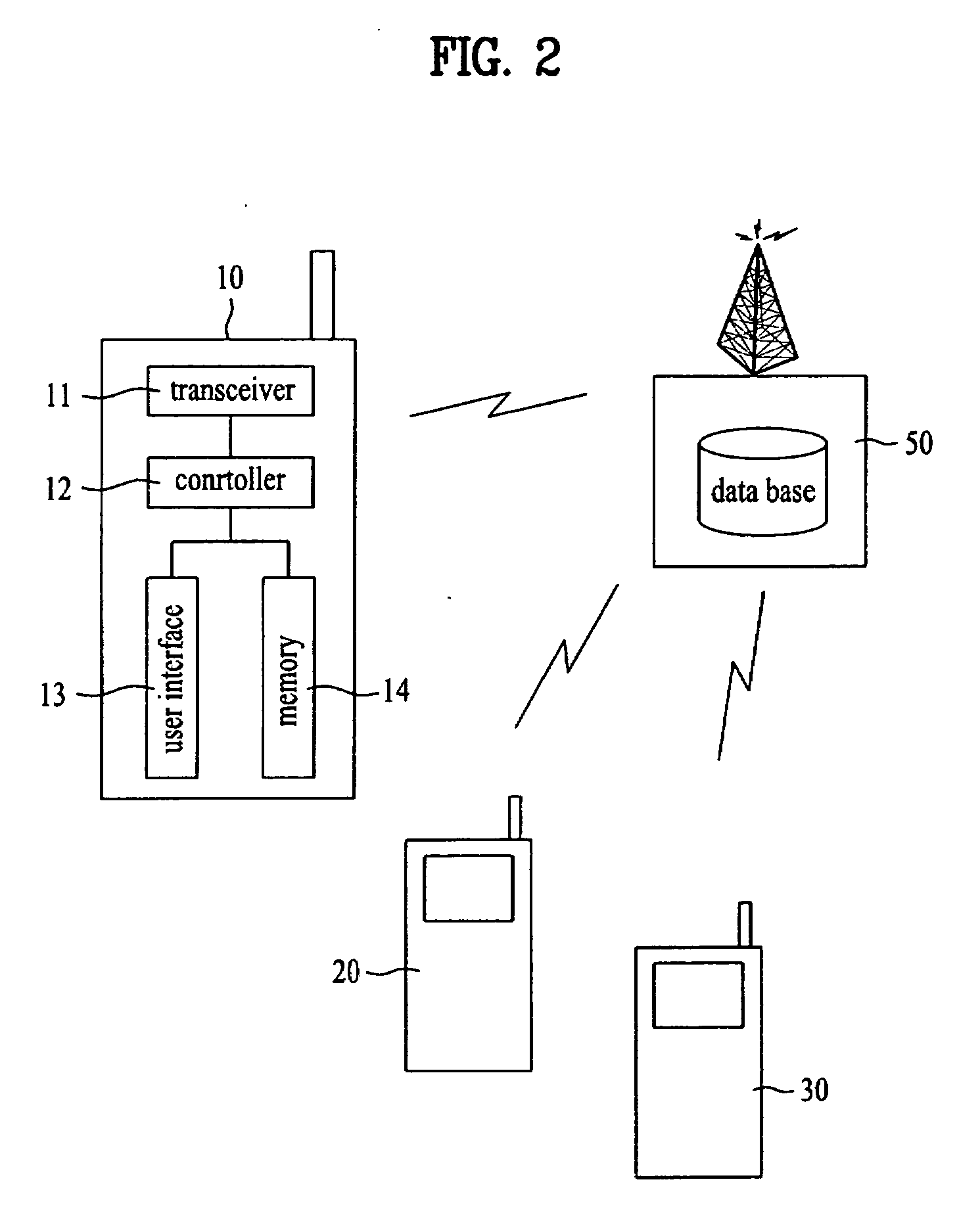
[0156] Secondly, a server retains a credibility rating for a specific sender identification number and is provided periodically or in signal transmission. Hence, a communication terminal's load in processing a reception blocking can be reduced.
[0157] It will be apparent to those skilled in the art that various modifications and variations can be made in the present invention without departing from the spirit or scope of the inventions. Thus, it is intended that the present invention covers the modifications and variations of this invention provided they come within the scope of the appended claims and their equivalents.

Problems solved by technology

Yet, the rapid increases of users and advertisements via communication networks occasionally need excessive calls and message / e-mail receptions and the like.
However, it is unable to substantially solve the conventional problems using the above blocking methods.

Method used


Image

  • Communication terminal and reception blocking method thereof
  • Communication terminal and reception blocking method thereof
  • Communication terminal and reception blocking method thereof

Examples


Embodiment Construction

[0041] Reference will now be made in detail to the preferred embodiments of the present invention, examples of which are illustrated in the accompanying drawings. Wherever possible, the same reference numbers will be used throughout the drawings to refer to the same or like parts.

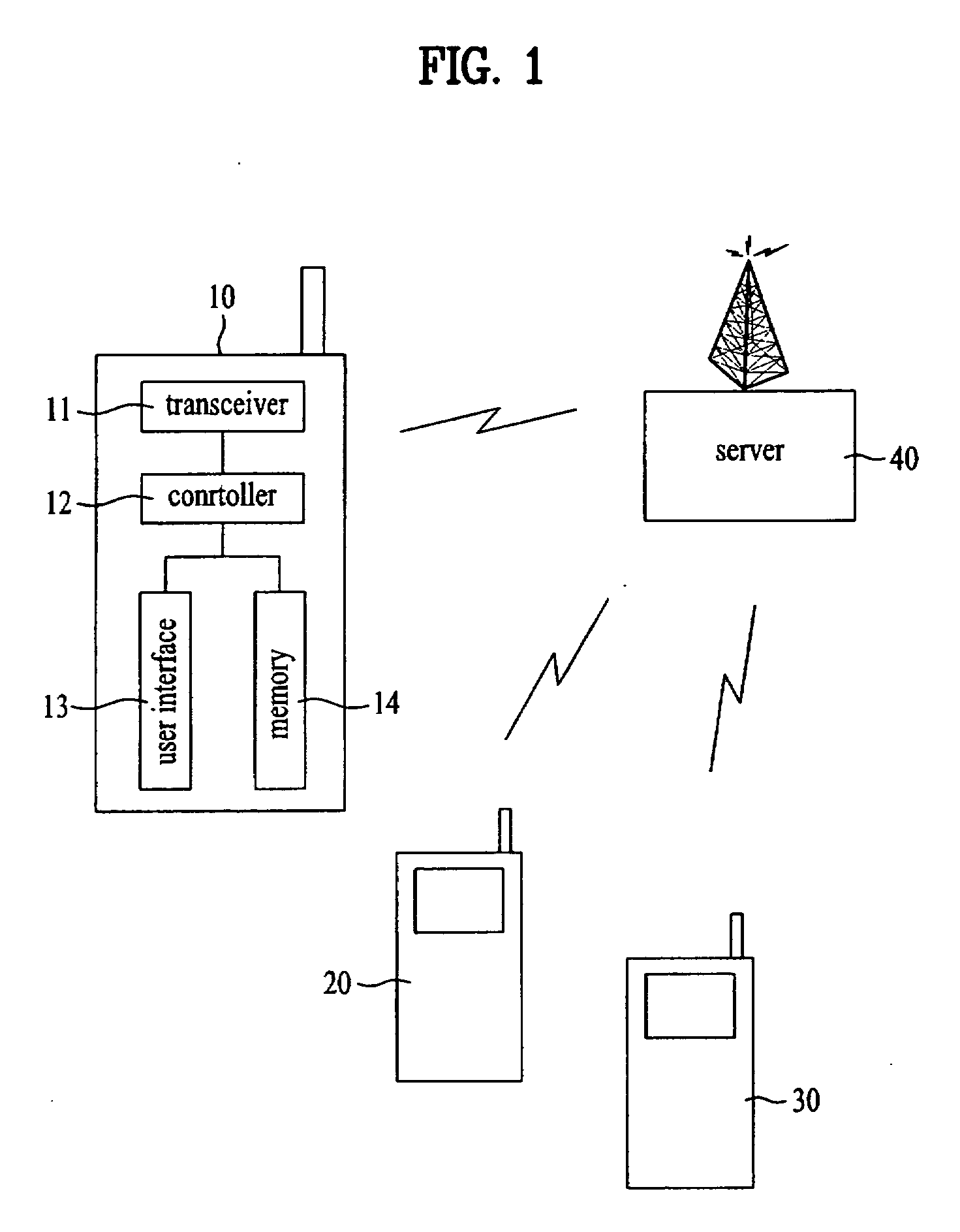
[0042] First of all, in the present invention, a signal transmitted from a specific identification number is blocked through interoperations between a server and communication terminals.

[0043] A server provides various communication services to a plurality of communication terminals. For instance, the server offers such a communication service as a short message service, a voice communication service, a video communication service, an e-mail service and the like.

[0044] The server relays signals according to the above-numerated services between communication terminals. An object of the present invention is to block the relayed signals in advance or process the relayed signals to block appropriately. And, ...


PUM


Abstract

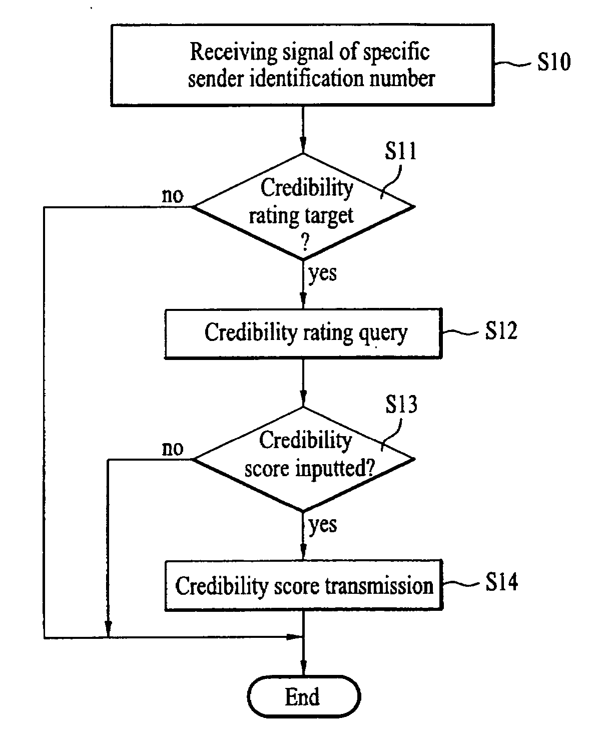
A communication terminal and reception blocking method thereof are disclosed, by which a signal of a sender having poor credibility can be blocked in advance, by which a plurality of recipients are able to rate a credibility of a specific sender to block a signal of the specific sender and by which information for the rating can be shared. The present invention includes the steps of setting a level of a reception blocking for a signal transmitted from a specific sender identification number, receiving credibility rating information for the specific sender identification number, and if a credibility rating of the specific sender identification number based on the credibility rating information belongs to a range of the set level, deciding the reception blocking for the signal transmitted from the specific sender identification number.

Description

[0001] This application claims the benefit of the Korean Patent Application No. 10-2005-0065408, filed on Jul. 19, 2005, which is hereby incorporated by reference as if fully set forth herein. BACKGROUND OF THE INVENTION [0002] 1. Field of the Invention [0003] The present invention relates to a reception blocking in a communication system, and more particularly, to a communication terminal and reception blocking method thereof. Although the present invention is suitable for a wide scope of applications, it is particularly suitable for blocking signals from a specific sender. [0004] 2. Discussion of the Related Art [0005] Generally, the evolution of communication technology and the generalization of communication terminals lead to the developments of various communication services. [0006] The communication services have evolved to a short message service for sending a short-length sentence from a voice communication oriented service. [0007] The developments of the communication servi...

Claims


Application Information

Patent Timeline
IPC IPC(8): G06F3/12
CPCH04M3/42059H04W4/16H04M2201/18H04M3/436H04M3/2281
Inventor LEE, DONG HYUN
Owner LG ELECTRONICS INC
Learn More