Directional loudspeaker control system

a control system and directional speaker technology, applied in the direction of gain control, loudspeakers, stereophonic arrangments, etc., can solve the problems of dampening of audio elements reaching the listening position directly from the first directional speaker, difficult to increase the energy of sound reflected, etc., to reduce the wiring distance between the speakers, improve the reflected sound, and improve the effect of sound localization

Active Publication Date: 2007-01-25
YAMAHA CORP
View PDF14 Cites 21 Cited by
  • Summary
  • Abstract
  • Description
  • Claims
  • Application Information

AI Technical Summary

Benefits of technology

[0012] In this invention, an audio element of the first sound emitted from the first directional speaker and reaching the listening position directly is dampened using the second sound emitted from the second directional speaker; hence, compared with the audio element reaching the listener from the first directional speaker directly, it is possible to enhance the reflected sound, which is produced by reflecting the first sound on the wall surface or the sound reflection board and then letting it reach the listener. Thus, it is possible to realize good sound localization similar to that realized by arranging speakers in the rear of the listener. In addition, the first directional speaker and the second directional speaker can produce virtual rear speakers. This eliminates the necessity of arranging rear speakers in the rear of the listening position; hence, it is possible to reduce wiring distances between the speakers.
[0013] A single array speaker is used to realize both the first directional speaker and second directional speaker; hence, even when another array speaker is used to perform sound cancellation using inverse phases, it is possible to prevent the listener from feeling uncomfortableness in hearing.
[0014] Furthermore, the sound subjected to dampening control by the second directional speaker is limited to a low-frequency sound; hence, it is possible to effectively dampen an audio element of the first sound emitted from the first directional speaker and reaching the listening position directly; and it is possible to avoid a problem in which the audio element to be dampened at the listening position increases in level unexpectedly.

Problems solved by technology

Since it is difficult to increase energy of sound reflected on the wall surface or the sound reflection board, the audio element reaching the listening position directly from the first directional speaker is dampened using the second sound emitted from the second directional speaker.

Method used


Image

  • Directional loudspeaker control system
  • Directional loudspeaker control system
  • Directional loudspeaker control system

Examples


first embodiment

[First Embodiment]

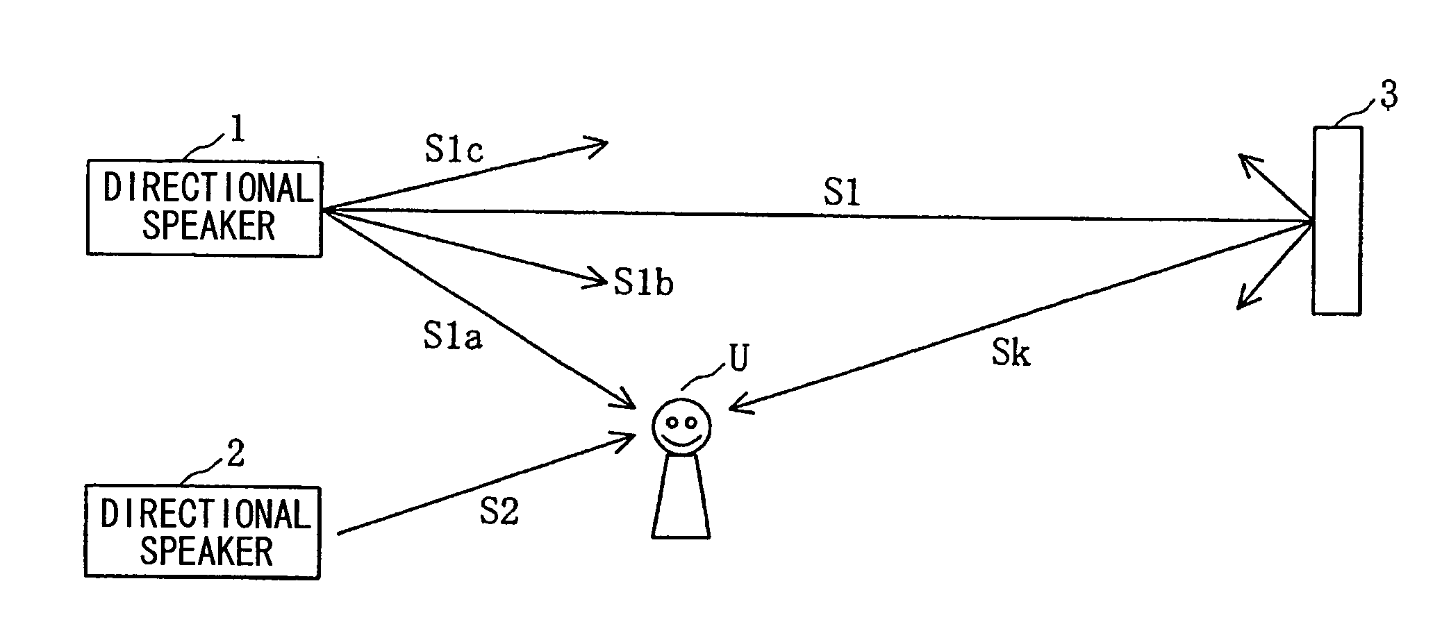
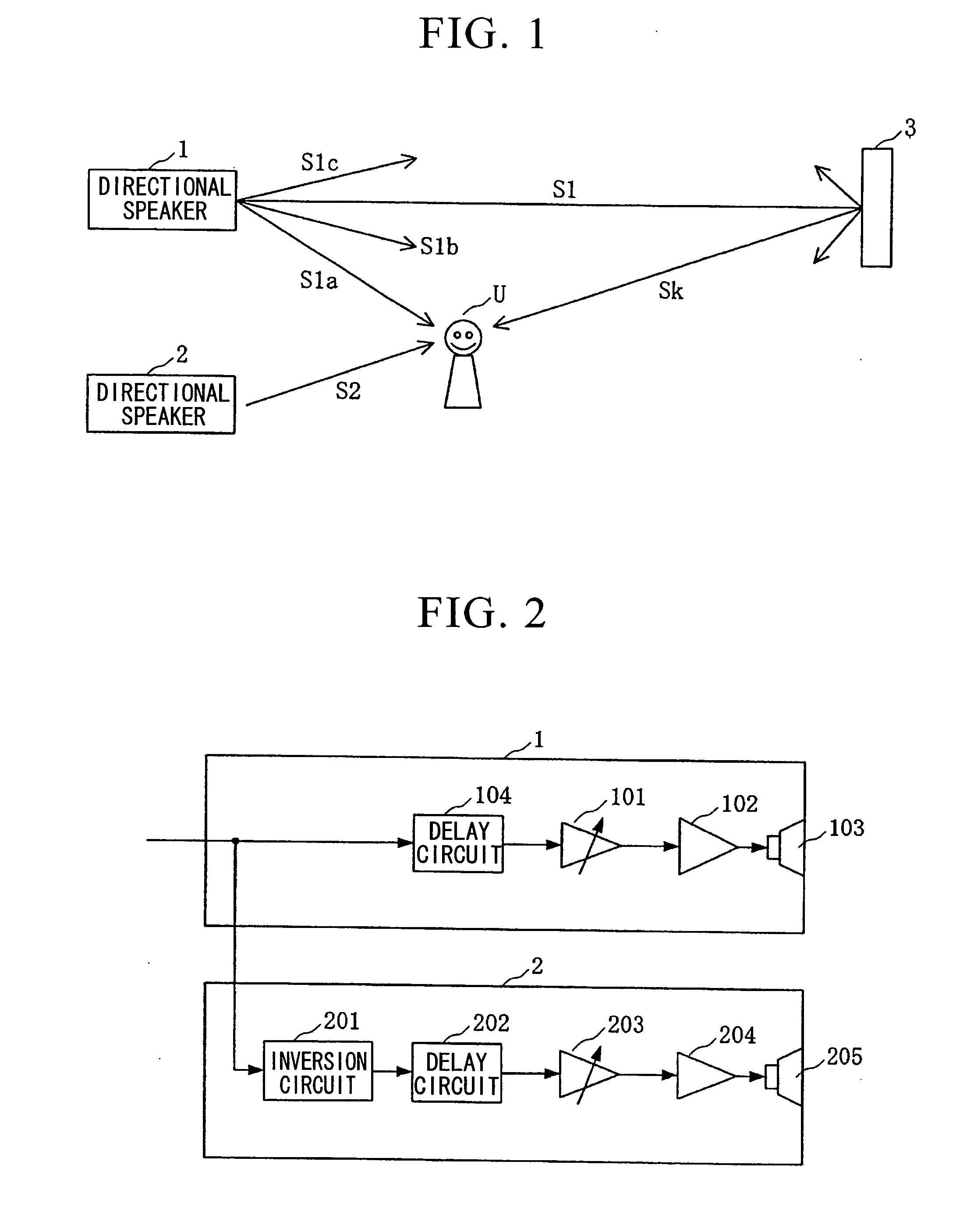
[0032]FIG. 1 is a block diagram showing the constitution of a directional speaker control system (i.e., a surround system) in accordance with a first embodiment of this invention. FIG. 1 shows only the constitution regarding a surround channel (i.e., a rear left signal SL or a rear right signal SR), and it does not show the constitution regarding a main channel (i.e., a main left signal L or a main right signal R).

[0033] The directional speaker control system according to the first embodiment of this invention includes a first directional speaker 1 for emitting a first sound S1 towards a wall surface of a listening room or a sound reflection board 3 and a second directional speaker 2 for emitting a second sound S2 whose phase is inverse to that of an audio element S1a of the first sound S1 and which reaches a listening position U directly.

[0034]FIG. 2 is a block diagram showing internal constitutions of the directional speakers 1 and 2. The first directional spea...

second embodiment

[Second Embodiment]

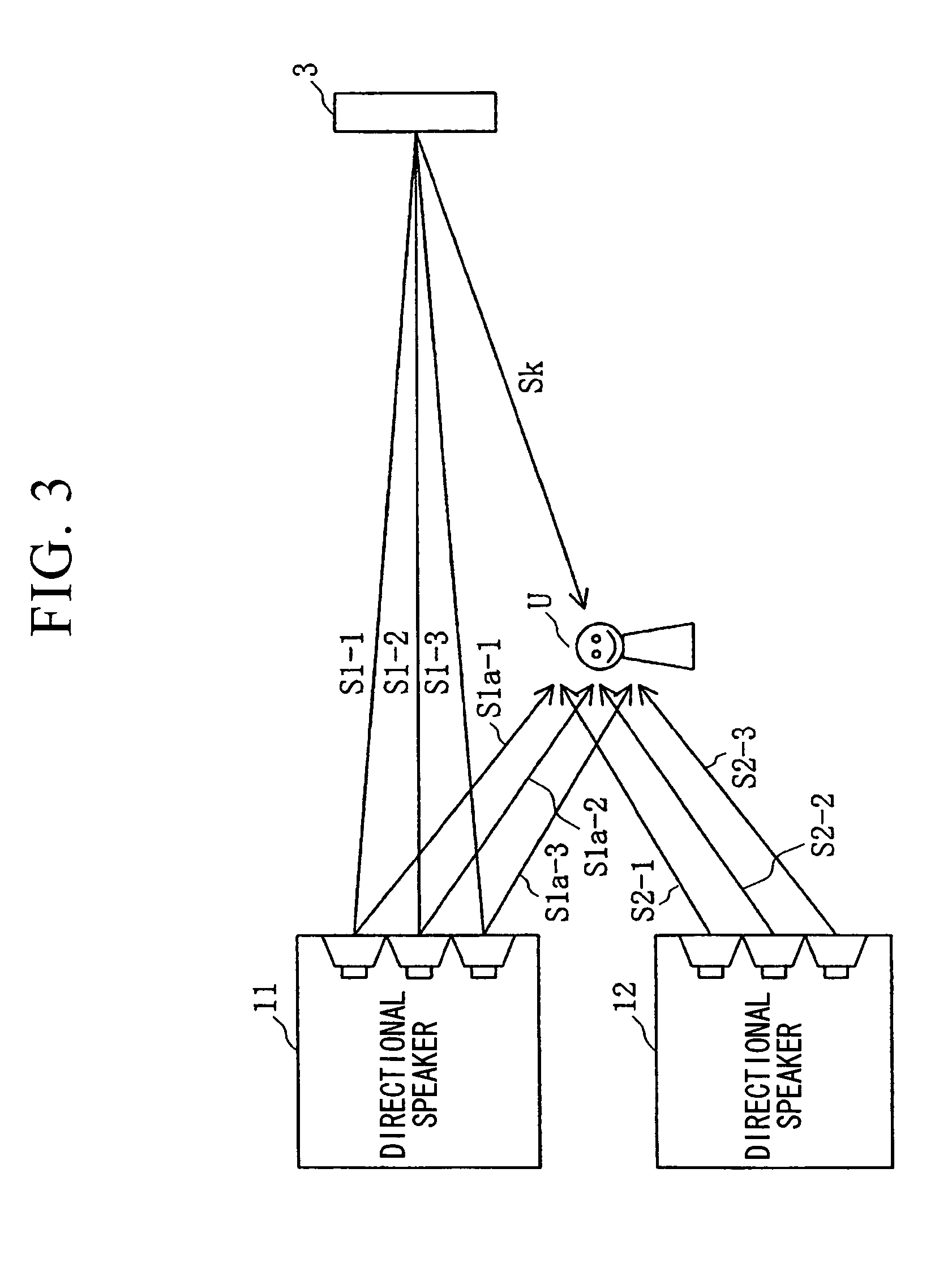
[0042] Next, a second embodiment of this invention will be described. FIG. 3 is a block diagram showing the constitution of a directional speaker control system of the second embodiment. The second embodiment is characterized in that array speakers are used for a first directional speaker 11 and a second directional speaker 12 respectively. FIG. 4 is a block diagram showing internal constitutions of the directional speakers 11 and 12.

[0043] The first directional speaker 11 includes a delay circuit 111 for applying a delay time, corresponding to the directivity (i.e., a focal position of a sound beam) to be realized, to an input surround-channel audio signal, plural gain adjustment circuits 112 (112-1 to 112-n) for adjusting gains of output signals of the delay circuit 111 to desired gains, plural amplifiers 113 (113-1 to 113-n) for amplifying output signals of the gain adjustment circuits 112, and plural speakers 114 (114-1 to 114-n) driven by the amplifiers 113....

third embodiment

[Third Embodiment]

[0060] Next, a third embodiment of this invention will be described. The aforementioned first and second embodiments need two directional speakers per channel; hence, four directional speakers in total are needed for a 2-channel surround system. In contrast, the third embodiment provides a practical example in which a 2-channel surround system is actualized using two directional speakers. FIG. 9 is a block diagram showing a directional speaker control system in accordance with the third embodiment, which is constituted using directional speakers 21 and 22. In FIG. 9, reference numeral 3-L designates a wall surface or sound reflection board that serves as an L-channel virtual rear speaker; and reference numeral 3-R designates a wall surface or sound reflection board that serves as an R-channel virtual rear speaker.

[0061] The directional speaker 21 functions as a first directional speaker for emitting a sound S1-L toward the wall surface or sound reflection board 3-...


PUM


Abstract

In a directional speaker control system for realizing good sound localization by correcting the directivity of a directional speaker, adapted to an audio surround system in which a desired sound is reflected on a wall surface or a sound reflection board so as to produce a virtual speaker, a first directional speaker emits a first sound toward the wall surface or sound reflection board so that the reflected sound reaches a prescribed listening position, and a second directional speaker emits a second sound, which comes to have an inverse phase with respect to an audio element of the first sound reaching the listening position directly, toward the listening position. Thus, it is possible to adequately dampen the audio element (particularly, low-frequency components) emitted directly toward the listening position from the first directional speaker; hence, it is possible to realize good sound localization.

Description

TECHNICAL FIELD [0001] This invention relates to directional speaker control systems in which sounds emitted from directional speakers such as array speakers are reflected on wall surfaces or sound reflection boards so as to produce virtual speakers. BACKGROUND ART [0002] Recently, various audio sources have been distributed and provided in the open market; and DVDs (digital versatile disks) store multi-channel audio signals of 5.1 channels, for example. Digital surround systems for reproducing audio sources have come to be widespread among general households. FIG. 14 is a plan view showing an example of a layout of speakers in a digital surround system, wherein reference numeral Zone designates a listening room for performing audio surround playback; reference numeral U designates a listening position; reference numeral SP-L designates a speaker for reproducing a main left signal L; reference numeral SP-R designates a speaker for reproducing a main right signal R; reference numeral...

Claims


Application Information

Patent Timeline
Patent Type & Authority Applications(United States)
IPC IPC(8): H04R29/00H04R5/02H04R1/40H04R3/12H04S1/00H04S3/00H04S7/00
CPCH04R1/403H04R3/12H04S3/00H04R2430/25H04R2203/12
Inventor KONAGAI, YUSUKE
Owner YAMAHA CORP
Why Eureka
Try Eureka